Air interface test system and method based on atomic coherence effect

An atomic and atomic gas cell technology, applied in the field of air interface test system based on atomic coherence effect, can solve the problems of low sensitivity, narrow frequency band that can be measured, and electric field interference to be measured, etc., and achieve high sensitivity, wide frequency band, and small interference. Effect

Pending Publication Date: 2022-01-28
SOUTH CHINA NORMAL UNIVERSITY
View PDF7 Cites 1 Cited by
  • Summary
  • Abstract
  • Description
  • Claims
  • Application Information

AI Technical Summary

Problems solved by technology

[0003] However, the probes used in the current multi-probe spherical near-field test system contain metal structures, which will cause interference to the electric field to be measured, and it needs to be calibrated before use, with low precision, low sensitivity, and narrow frequency bands that can be measured; It is necessary to replace the probe when the frequency point of the equipment is high, resulting in high test cost

Method used


Image

  • Air interface test system and method based on atomic coherence effect
  • Air interface test system and method based on atomic coherence effect
  • Air interface test system and method based on atomic coherence effect

Examples


Embodiment 1

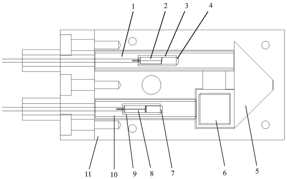
[0048] Such as figure 1 As shown, the present invention provides a prism type atomic antenna probe, comprising an alkali metal atomic gas chamber 6, a prism 5, the first optical fiber 2 with a pigtail ferrule, the second optical fiber 8 with a pigtail ferrule, the first gradient A refractive index lens 4 , a second gradient index lens 7 , a first small glass sleeve 3 , a second small glass sleeve 9 , a first large glass sleeve 1 , a second large glass sleeve 10 and a protective shell 11 .

[0049]The prism 5 is a triangular prism or a trapezoidal prism for reflecting laser light. The first optical fiber 2 with a pigtail ferrule and the first gradient index lens 4 are fixed inside the first small glass sleeve 3 with optical glue, and then this The whole part is fixed inside the first large glass casing 1 with optical glue, and then the first large glass casing 1 and the upper part of the prism 5 are glued together with optical glue.

[0050] The second optical fiber 8 with a p...

Embodiment 2

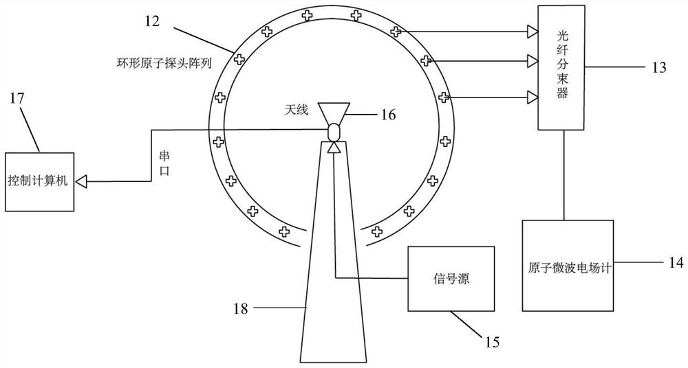
[0055] Such as figure 2 As shown, the present invention provides an air interface test system based on the atomic coherence effect, which includes an annular atomic probe array 12 composed of 16 prism-type atomic antenna probes, an optical fiber beam splitter 13, an atomic microwave electric field meter 14, a signal source 15, and Measuring antenna 16, control computer 17 and antenna turntable 18.

[0056] Among them, 16 prism-type atomic antenna probes are evenly arranged on a circular scanning support at specific angular intervals to form a circular atomic probe array 12 for receiving signals; a fiber optic beam splitter 13 is used to connect the circular atomic probe array 12 to the atomic The microwave electric field meter 14, the atomic microwave electric field meter 14 provides the ring-shaped atomic probe array 12 with a specific frequency laser and is used for data collection. The signal source 15 is used to provide signals for the antenna under test 16 , and the con...

Embodiment 3

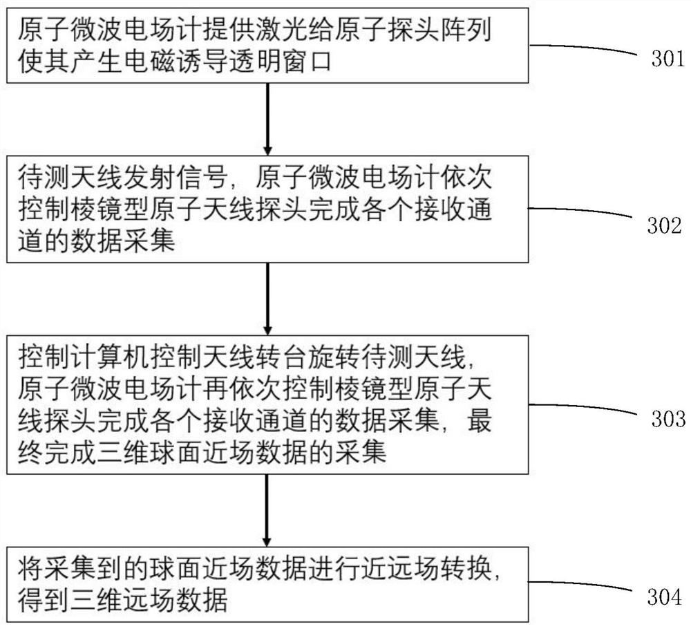
[0058] Such as image 3 As shown, the present invention provides a kind of air interface test method based on atomic coherence effect, comprising the following steps:

[0059] Step 301, the atomic microwave electric field meter 14 provides laser light to the ring-shaped atomic probe array 12 to generate an electromagnetically induced transparent window;

[0060] Step 302, the signal source 15 provides a signal to the antenna under test 16, the antenna under test 16 transmits the signal, and the atomic microwave electric field meter 14 sequentially controls the prism type atomic antenna probe to complete the data acquisition of each receiving channel;

[0061] Step 303, the control computer 17 controls the antenna turntable 18 to rotate the antenna 16 to be tested, and the atomic microwave electric field meter 14 sequentially controls the prism-type atomic antenna probe to complete the data collection of each receiving channel, and finally completes the collection of three-dime...


PUM


Abstract

The invention discloses an air interface test system and method based on an atomic coherence effect, and the method comprises the steps: uniformly arranging a plurality of prism-type atomic antenna probes at specific angle intervals on a circular scanning support in a microwave darkroom according to the requirements of a sampling theorem to form an annular atomic probe array; connecting the annular atom probe array to the optical fiber beam splitter through an optical fiber; placing a to-be-tested antenna on the rotary table, and guaranteeing that the phase center of the to-be-tested antenna is at the circle center of the scanning support; taking the to-be-tested antenna as a transmitting antenna, and enabling the atomic microwave electric field meter to sequentially control the prism type atomic antenna probe to complete data acquisition of each receiving channel; enabling a control computer to control the antenna turntable to rotate the to-be-tested antenna to complete three-dimensional spherical near-field data acquisition; and performing near-far field transformation on the collected spherical near-field data to obtain three-dimensional far-field data. According to the invention, self-calibration can be realized, the to-be-tested electric field is not interfered, the sensitivity is high, the measurable frequency band is wide, the air interface test precision is greatly improved, and the test cost is reduced.

Description

technical field [0001] The invention relates to the technical field of electromagnetic compatibility testing, in particular to an air interface testing system and method based on atomic coherence effects. Background technique [0002] In recent years, with the rapid development of mobile communication networks, the rapid development of mobile communication antenna technology has been promoted, so this has brought huge challenges to the test function, test accuracy and test efficiency of traditional antenna measurement sites. The conventional far-field measurement method requires a large measurement site, slow test speed, and high construction costs, which cannot meet the test requirements of modern antennas. In addition, for many modern communication devices, only the results measured by the integrated air interface test method can effectively reflect their performance indicators. Therefore, test systems such as multi-probe spherical near-field, single-probe near-field, and...

Claims


Application Information

Patent Timeline
Patent Type & Authority Applications(China)
IPC IPC(8): G01R29/10
CPCG01R29/10
Inventor 陈常军廖开宇边武张新定颜辉
Owner SOUTH CHINA NORMAL UNIVERSITY
Why Eureka
Try Eureka