
Intelligent manufacturing platform-based automatic assembling mechanism for power equipment

A technology of intelligent manufacturing and power equipment, applied in the direction of manufacturing tools, metal processing equipment, switchgear, etc., can solve the problems of increased production cost of devices, low degree of automation, cumbersome pressing methods, etc., to achieve improved work efficiency, convenient operation, Realize the effect of continuous operation

Active Publication Date: 2022-01-28
HEBEI UNIVERSITY OF SCIENCE AND TECHNOLOGY
View PDF6 Cites 1 Cited by
  • Summary
  • Abstract
  • Description
  • Claims
  • Application Information

AI Technical Summary

Problems solved by technology

[0004] But this device still has certain deficiencies. 1. The lamination method adopted by this device requires manual placement of the first backing plate and frame film a in sequence, then placing 3CCM on frame film a, and then placing frame film b in sequence and the second backing plate, and finally press them. This pressing method is more cumbersome and difficult to achieve continuous operation, and the work efficiency is low; 2. The device is prone to shaking during the pressing process, resulting in misalignment of the pressing and affecting the product. 3. The device has a low degree of automation, which makes it difficult to achieve mass production, which increases the production cost of the device and affects the company's income

Method used


Image

  • Intelligent manufacturing platform-based automatic assembling mechanism for power equipment
  • Intelligent manufacturing platform-based automatic assembling mechanism for power equipment
  • Intelligent manufacturing platform-based automatic assembling mechanism for power equipment

Examples


Embodiment Construction

[0037] In order to make the purpose, technical solutions and advantages of the embodiments of the present invention clearer, the technical solutions in the embodiments of the present invention will be clearly and completely described below in conjunction with the accompanying drawings. Apparently, the described embodiments are some, not all, embodiments of the present invention.

[0038] Therefore, the following detailed description of the embodiments of the present invention is not intended to limit the scope of the claimed invention, but merely represents some embodiments of the present invention. Based on the embodiments of the present invention, all other embodiments obtained by persons of ordinary skill in the art without making creative efforts belong to the protection scope of the present invention.

[0039] It should be noted that, in the case of no conflict, the embodiments of the present invention and the features and technical solutions in the embodiments can be com...


PUM


Abstract

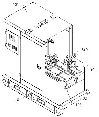
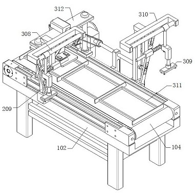
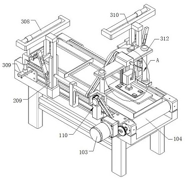
The invention provides an intelligent manufacturing platform-based automatic assembling mechanism for power equipment. The automatic assembling mechanism comprises a base and a box body arranged at the top of the base. The automatic assembling mechanism further comprises a supporting table fixedly connected in the box body through a connecting column; a driving motor is connected to the outer wall of the supporting table; a conveying belt component is rotatably connected in the supporting table; the top of the supporting table is connected with a supporting column; the top of the supporting column is provided with a reciprocating device matched with the end, away from the driving motor, of an auxiliary device and the conveying belt component; and the side wall of the supporting table is provided with a first picking and placing mechanism and a second picking and placing mechanism; and a first placing rack and a second placing rack which are matched with the first picking and placing mechanism and the second picking and placing mechanism are arranged in the box body. The mechanism is simple in structure and convenient to operate; the working process of an operator is simplified;it is guaranteed that the pressing quality is not affected by the shaking condition in the pressing process; the production quality of the device is guaranteed; the production cost of the device is reduced; and the factory income is increased.

Description

technical field [0001] The invention relates to the field of hydrogen fuel cell production, in particular to an automatic assembly mechanism for power equipment based on an intelligent manufacturing platform. Background technique [0002] Fuel cells are promising new power sources, generally using hydrogen, carbon, methanol, borohydride, coal gas or natural gas as fuel, as the negative electrode, and oxygen in the air as the positive electrode. The main difference between it and a general battery is that the active material of a general battery is pre-placed inside the battery, so the battery capacity depends on the amount of active material stored; while the active material (fuel and oxidant) of a fuel cell is reacted at the same time. Constant input, so this type of battery is really just an energy conversion device. This type of battery has the advantages of high conversion efficiency, large capacity, high specific energy, wide power range, and no charging. The fuel cel...

Claims


Application Information

Patent Timeline
Patent Type & Authority Applications(China)
IPC IPC(8): H02B3/00B23P19/02B23P19/00
CPCH02B3/00B23P19/02B23P19/003B23P19/006
Inventor 庞雅静王震洲
Owner HEBEI UNIVERSITY OF SCIENCE AND TECHNOLOGY
Learn More