
Unmature dendritic cell resuscitation device

An immature technology of dendritic cells, applied in tissue cell/virus culture devices, biochemical cleaning devices, enzymology/microbiology devices, etc., can solve the problem of submersion of cryopreservation tubes below the water surface and fatigue of staff wrists , cell pollution and other issues, to achieve the effect of reducing heat loss, good energy saving effect, and simple operation

Active Publication Date: 2022-02-01
迈赛凯尔(山东)生命科学有限公司
View PDF9 Cites 0 Cited by
  • Summary
  • Abstract
  • Description
  • Claims
  • Application Information

AI Technical Summary

Problems solved by technology

However, the long-term violent shaking of the artificially resuscitated cells often leads to the fatigue of the staff's wrists, which can easily cause the cryopreservation tube to be submerged below the water surface, and easily cause pollution and damage to the cells. Therefore, we propose a new type of immature dendritic cell recovery device

Method used


Image

  • Unmature dendritic cell resuscitation device
  • Unmature dendritic cell resuscitation device
  • Unmature dendritic cell resuscitation device

Examples


Embodiment 1

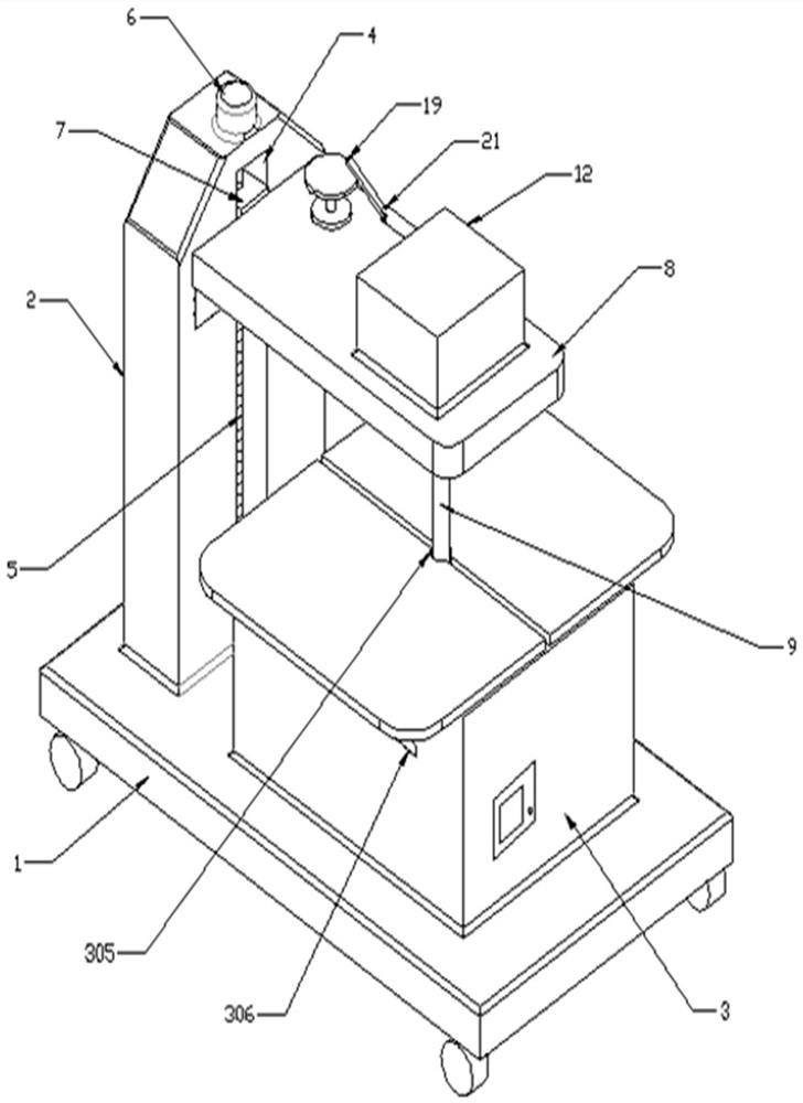
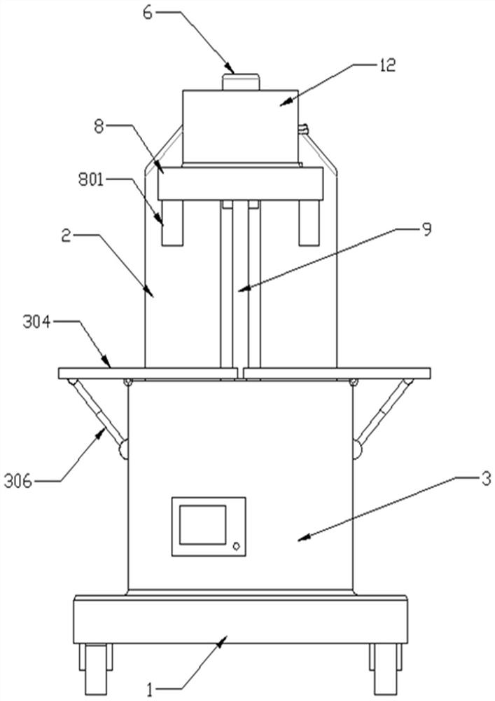
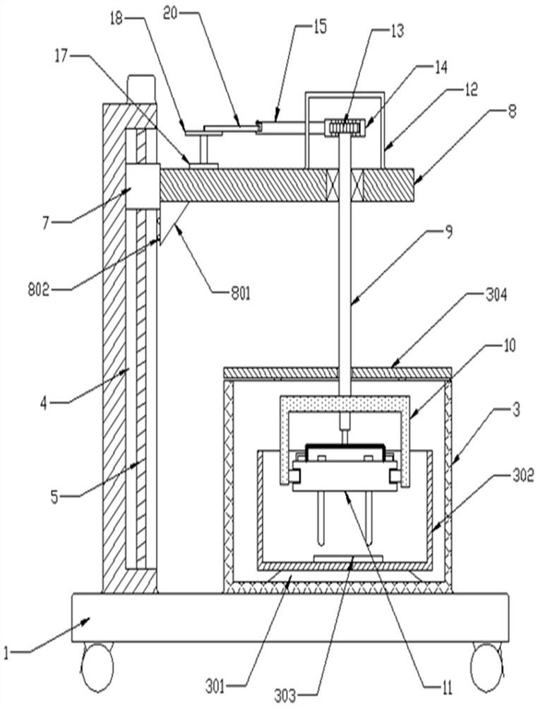
[0026] See Figure 1-5 As shown, the present embodiment is an immature dendritic cell resuscitation device, including a base 1, and a fixed seat 2 is connected to the top left side of the bottom seat 1, and a heat casing 3 is connected to the top right side of the base 1. 2 The right side of the right side is opened, and the guide groove 4 is rotated in the guide slot 4, and the upper end of the rod 5 is mounted, and the outer wall of the rod 5 is connected to the nut seat 7, the right end of the nut 7 The support station 8 is connected, the right direction of the support table 8 is rotated and the deflection shaft 9 is connected, and the lower end of the deflection shaft 9 is connected to the U-shaped seat 10, and the lower end of the U-shaped seat 10 detachable is attached to the positioning station 11.

[0027] The mounting frame 301 is attached to the inner cavity bottom of the insulation shell 3, and the upper end of the mounting frame 301 is connected to the water bath 302, a...

Embodiment 2

[0032] On the basis of the first example, the drive case 12 is connected to the right side of the top of the support table 8, and the deflection shaft 9 extends into one end of the transmission case 12 is connected to the straight gear 13, and the rear end meshing of the straight gear 13 is connected to the straight rack 14. The left end of the straight rack 14 has a reciprocating rod 15, and the left end of the transmission case 12 is provided with the guide hole 16 supplied to the retrograft 15. The top left side of the top portion of the support table 8 is fitted with a steering motor 17, and the top power of the steering motor 17. The output terminal is connected to the turntable 18, and the top of the turntable 18 is hinged by the first pin shaft 19, and the right end of the traction rod 20 is hinged to the back rod 15 by the second pin shaft 21.

[0033] The positioning table 11 penetrates in the vertical direction, and the cell test tube is inserted in the positioning hole ...


PUM


Abstract

The invention discloses an immature dendritic cell resuscitation device, and relates to the technical field of biological experimental equipment.The immature dendritic cell resuscitation device comprises a base, the left side of the top of the base is connected with a fixing seat, the right side of the top of the base is connected with a heat insulation shell, the right side wall of the fixing seat is provided with a guide groove, and a lead screw is rotationally connected into the guide groove; and a driving motor is installed at the upper end of the lead screw, a nut seat is in threaded connecting with the outer wall of the lead screw, a support table is connected to the right end of the nut seat, a deflection shaft is rotationally connected to the right portion of the support table, a U-shaped seat is connected to the lower end of the deflection shaft, and a positioning table is detachably installed at the lower end of the U-shaped seat. The device is reasonable in structural design, simple to operate and high in automation degree, manual handheld oscillation is not needed, the labor intensity is reduced, and the recovery efficiency of the immature dendritic cells is improved.

Description

Technical field [0001] The present invention relates to the technical field of biological experiment devices, and more particularly to an immature dendritic cell resuscitation device. Background technique [0002] Dendritic cells are currently known to have the strongest antigen induced cells, also a nerve cell, reaching a multi-tree mosity or counterfeit protrusion during ripening, and the start of cell experiments often needs After the frozen cells were cultured and passed in the cell recovery, and the current cell recovery relied in manual operation. The existing artificial resuscitation cells is to closely sandwich the liquid nitrogen tube with the lying tube. The tube is placed in a preheated 37 ° C water bath in a preheated 37 ° C water bath, and the cell recovery is completed when the cells in the frozen tube are completely dissolved. However, the long-discrete of artificial recovery cells often leads to the loss of staff wrist, which is easily impregnated by the frozen co...

Claims


Application Information

Patent Timeline
Patent Type & Authority Applications(China)
IPC IPC(8): C12M3/00C12M1/24C12M1/02
CPCC12M23/08C12M23/48C12M23/50C12M23/52C12M27/16C12M37/04C12M41/12C12M41/22
Inventor 李春雨纪元王学动闫奔任美佳覃婷王志媛冯丽敏张静
Owner 迈赛凯尔(山东)生命科学有限公司
Learn More