


Quick Research
Generate reliable direction feasibility study reports for your R&D in just a few steps.

Technical Q&A
Discover and master advanced knowledge NOW. Basics, ideas, possibilities, all at once.

Find Solutions
As an expert in R&D theories, this can generate solutions to your technical problems instantly.

Evaluate Feasibility
Analyze your overall solution with one click, know your potential R&D risks in advance.

Monitor Landscape
Get weekly tech updates, stay abreast of the latest tech innovations and key insights.
Nano magnetofluid hydraulic pump station and using method thereof
A nano-magnetic fluid and hydraulic pumping station technology, applied in the direction of pumps, pump control, pump components, etc., can solve the problems of hydraulic system reduction and low work efficiency, and achieve the effect of reducing viscous power loss, simple structure, and high hardness
- Summary
- Abstract
- Description
- Claims
- Application Information
AI Technical Summary
Problems solved by technology
Method used
Image

Examples
Embodiment 1
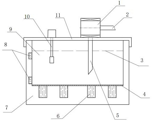
[0052] Example 1: as figure 1 As shown, a nano-magnetic fluid hydraulic pump station includes a nano-magnetic fluid hydraulic pump 1, an oil outlet pipeline 2, a vibrating steel plate 4, an oil suction pipeline 5, an ultrasonic vibrator 6, a fuel tank box 7, a dispersion detector 8, and a nano-magnetic fluid. Fluid 9 , temperature sensor 10 and fuel tank cover 11 . The nano-magnetic fluid gear pump 1 is fixedly installed on the fuel tank cover 11, the oil outlet pipe 2 and the oil suction pipe 5 are connected with the nano-magnetic fluid gear pump 1 through threads, the vibrating steel plate 4 is connected with the fuel tank case 7 by welding, and the ultrasonic vibrator 6 is installed At the bottom of the fuel tank body 7 and in contact with the vibrating steel plate 4, the dispersion detector 8 is fixedly installed on the side wall of the fuel tank body 7, the temperature sensor 10 is fixedly installed on the fuel tank cover plate 11, and its probe is located below the liqui...
Embodiment 2
[0082] Example 2: as Figure 5 As shown, a method for realizing viscosity-temperature performance compensation by utilizing the nano-magnetic fluid hydraulic pump station, the specific steps are:
[0083] Step1: Monitor the temperature of the magnetic nanofluid 9 and collect its temperature data;
[0084] Step2: Pass the direct current into the electromagnetic coil to generate a constant magnetic field, so that the magnetic field covers the nano-magnetic fluid 9, and at the same time, convert the direct current into a digital signal and input it into the temperature control module;
[0085] Step3: Judge the temperature of the nano-magnetic fluid 9 through the temperature control module, and judge whether it reaches the rated minimum working temperature;
[0086] Step4: If the temperature of the nano-magnetic fluid 9 is lower than the rated minimum operating temperature, connect the AC power supply to the electromagnetic coil to generate an alternating magnetic field, so that ...
Embodiment 3
[0090] Embodiment 3: a kind of method that utilizes described nanometer magnetic fluid hydraulic pump station to realize medium dispersion stability detection and redispersion, and concrete steps are:
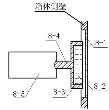
[0091] Step1: Turn on the force sensor 8-5, perform calibration and zero adjustment, and set the glass window 8-1 at the position where the dispersion detector 8 is installed on the mailbox wall.
[0092] Step2: Adjust the distance between the upper and lower dispersity detectors 8 and the tested medium, so that the distance between the permanent magnets 8-2 of the two dispersity detectors 8 and the glass window 8-1 is both 0.1 mm.
[0093] The attractive force between the permanent magnet and the nanomagnetic fluid is very weak. It needs to be close to collect, and the wall of the fuel tank is thick due to the support function and the installation of other devices.
[0094] Therefore, arranging a glass window structure on the wall of the fuel tank can make the permanent magnet ...
PUM
| Property | Measurement | Unit |
|---|---|---|
| The average particle size | aaaaa | aaaaa |
Abstract
Description
Claims
Application Information
 - R&D Engineer
- R&D Manager
- IP Professional
- Industry Leading Data Capabilities
- Powerful AI technology
- Patent DNA Extraction
Browse by: Latest US Patents, China's latest patents, Technical Efficacy Thesaurus, Application Domain, Technology Topic, Popular Technical Reports.
© 2024 PatSnap. All rights reserved.Legal|Privacy policy|Modern Slavery Act Transparency Statement|Sitemap|About US| Contact US: help@patsnap.com