
Hydraulic control system suitable for pressing artillery and control method of hydraulic control system

A hydraulic control system and artillery technology, which is applied to fluid pressure actuation system components, fluid pressure actuation devices, servo motors, etc., and can solve problems such as increased difficulty in debugging control parameters, long dynamic adjustment time, and system instability , to achieve the effect of strengthening the anti-shock ability, reducing adverse effects, and improving smoothness and stability

Active Publication Date: 2022-02-01
中国兵器装备集团自动化研究所有限公司
View PDF8 Cites 0 Cited by
  • Summary
  • Abstract
  • Description
  • Claims
  • Application Information

AI Technical Summary

Problems solved by technology

[0004] The technical problem to be solved by the present invention is: the existing hydraulic pressure control system of suppressing artillery is prone to problems such as long dynamic adjustment time, system instability, and speed ring oscillation, which increases the difficulty of debugging control parameters
The purpose is to provide a hydraulic control system and its control method suitable for suppressing artillery, and to solve the defects existing in the existing hydraulic control system for suppressing artillery

Method used


Image

  • Hydraulic control system suitable for pressing artillery and control method of hydraulic control system
  • Hydraulic control system suitable for pressing artillery and control method of hydraulic control system

Examples


Embodiment 1

[0034] figure 1 It is a schematic diagram of the structure and working principle of the traditional hydraulic control system. It can be seen from the figure that the traditional hydraulic control system directly feeds back the angle value obtained in the position loop to the position regulator and PID regulator 2. Due to the strong hysteresis and nonlinearity of each link of the hydraulic system, it causes dynamic adjustment. A series of problems such as long time, unstable system, vibration of speed ring, etc.

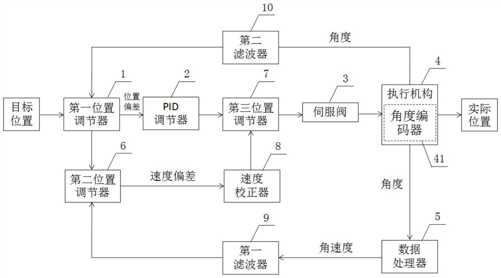
[0035] In order to solve the shortcomings of the traditional hydraulic control system, this embodiment improves a hydraulic control system suitable for suppressing artillery reference figure 2 , including a first position regulator 1, a PID regulator 2, a servo valve 3, an actuator 4, a data processor 5, a second position regulator 6, a third position regulator 7 and a speed corrector 8; the first The position regulator 1, the PID regulator 2, the servo valve 3 and...

Embodiment 2

[0040] A control method for a hydraulic control system suitable for suppressing artillery, comprising the following steps:

[0041] Step 1: Obtain the angle value of the suppressed gun barrel from the angle encoder, and feed back the angle value to the first position regulator;

[0042] Step 2: using the data processor to perform differential processing on the angle value to obtain the angular velocity of the suppressed gun barrel, and send the angular velocity to the second position regulator;

[0043] Step 3: Obtain the target position of the suppressed artillery barrel, and obtain the position deviation of the suppressed artillery barrel by using the first position regulator, the target position and the angle value;

[0044] Step 4: Calculate and obtain the target speed for suppressing the gun barrel according to the position deviation;

[0045] Step 5: Using the second position regulator to compare and analyze the target speed and angular speed to obtain a speed deviation...


PUM


Abstract

The invention discloses a hydraulic control system suitable for pressing artillery. The hydraulic control system comprises a first position regulator, a PID regulator, a servo valve, an execution mechanism, a data processor, a second position regulator, a third position regulator and a speed corrector. Wherein the first position regulator, the PID regulator, the servo valve and the actuating mechanism are connected in sequence; the second position regulator is connected between the first position regulator and the PID regulator, the third position regulator is connected with the PID regulator, and the third position regulator is connected with the servo valve; the execution mechanism is connected with the data processor and the first position regulator; the data processor is connected with the second position regulator; the second position regulator is connected with a speed corrector; and the speed corrector is connected with the third position regulator. According to the invention, adverse effects caused by speed signal distortion in a traditional hydraulic control system can be reduced, the anti-oscillation capability of the system is enhanced, the stability and stability of the system can be improved, and the difficulty of control parameter adjustment can be reduced.

Description

technical field [0001] The invention relates to the technical field of hydraulic servo systems, in particular to a hydraulic control system suitable for suppressing artillery and a control method thereof. Background technique [0002] As the hydraulic servo system is more and more widely used in suppressing artillery, the nonlinearity of the hydraulic control system and the large inertia of the artillery pose new challenges to the control system. However, in actual engineering, due to the limitation of the angular position sensor and its signal acquisition system, the speed obtained by this method is inaccurate, and because of the hysteresis and strong nonlinearity of each link of the hydraulic system, it is easy to cause long dynamic adjustment time. A series of problems such as system instability and speed loop oscillation have increased the difficulty of debugging control parameters. [0003] In view of this, this application is proposed. Contents of the invention [...

Claims


Application Information

Patent Timeline
Patent Type & Authority Applications(China)
IPC IPC(8): F15B11/04F15B13/02F15B21/02
CPCF15B11/04F15B13/02F15B21/02
Inventor 王咸锋魏正兵姚毅曾刊雷凌毅陶俊瞳
Owner 中国兵器装备集团自动化研究所有限公司
Learn More