
External heating type solid hydrogen storage system and hydrogen charging and discharging method thereof

A solid-state hydrogen storage technology, applied in the field of hydrogen energy, can solve the problems of low thermal conductivity of hydrogenation products, unfavorable hydrogen charging and discharging reactions, and slow start-up of equipment, and achieve the effects of simple structure, reduced start-up time, and increased filling capacity

Active Publication Date: 2022-02-01
氢储(上海)能源科技有限公司
View PDF7 Cites 1 Cited by
  • Summary
  • Abstract
  • Description
  • Claims
  • Application Information

AI Technical Summary

Problems solved by technology

Conventional heating methods include electric heating rod heating and heat conduction oil heating, etc. However, due to the low thermal conductivity of the hydrogenation product of the hydrogen storage material, these heating methods based on heat conduction take a long time, the equipment starts slowly, and usually requires several times of heating. Hours to reach hydrogen charging or hydrogen discharging temperature
In addition, the temperature difference between different positions in the hydrogen storage container is very large, the temperature of the magnesium alloy material near the heat exchange tube or heating rod is high, and the temperature far away from the heat exchange tube or heating rod is very low, and the uneven heating is serious, which is not conducive to The progress of the hydrogen charging and discharging reaction

Method used


Image

  • External heating type solid hydrogen storage system and hydrogen charging and discharging method thereof
  • External heating type solid hydrogen storage system and hydrogen charging and discharging method thereof

Examples


Embodiment Construction

[0018] The following are specific embodiments of the present invention and in conjunction with the accompanying drawings, the technical solutions of the present invention are further described, but the present invention is not limited to these embodiments.

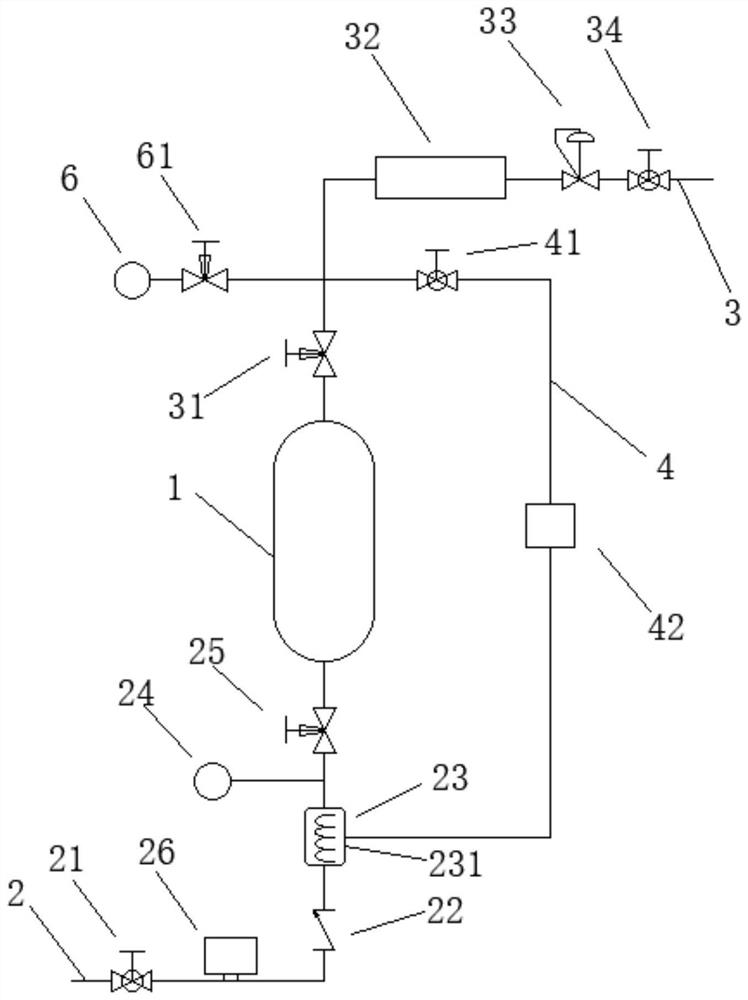
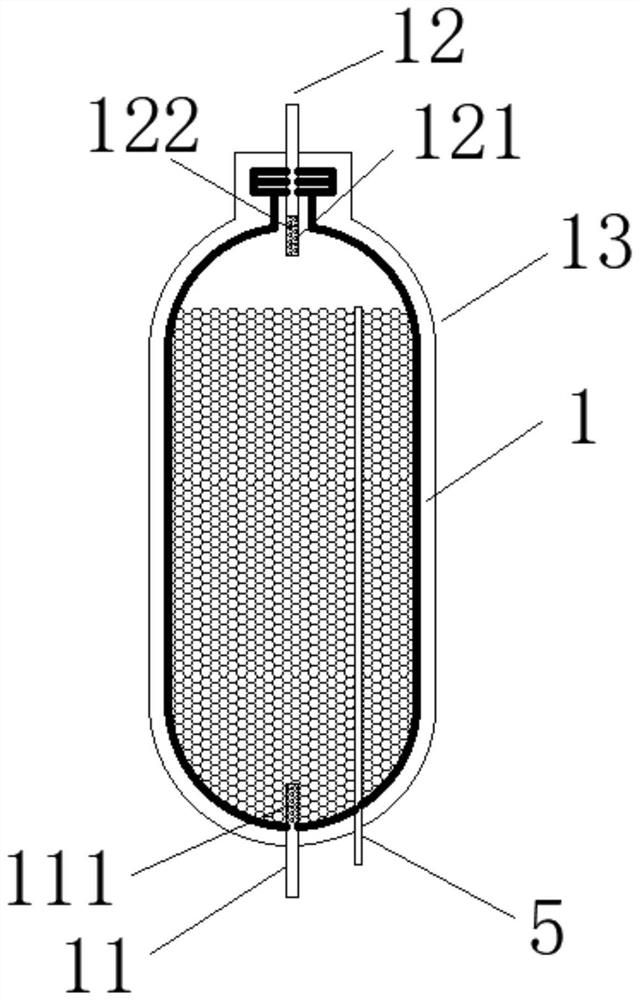
[0019] Such as figure 1 and 2 As shown, an externally heated solid-state hydrogen storage system of the present invention includes a hydrogen storage tank 1, an air inlet pipe 2, an air outlet pipe 3 and a circulation pipe 4. The hydrogen storage tank 1 is filled with a magnesium-based hydrogen storage alloy, and the hydrogen storage tank 1 is provided with at least one temperature sensor sleeve 5 along the axial direction, and a plurality of first temperature sensors (not shown in the figure) are installed in the temperature sensor sleeve 5 for real-time monitoring of the temperature at different positions in the hydrogen storage tank 1 The air inlet pipe 2 and the air outlet pipe 3 are respectively connected with the ai...


PUM


Abstract

The invention discloses an external heating type solid hydrogen storage system and a hydrogen charging and discharging method thereof. The system comprises a hydrogen storage tank, a gas inlet pipe, a gas outlet pipe and a circulating pipe, at least one temperature sensor sleeve is arranged in the hydrogen storage tank in the axial direction, and a plurality of first temperature sensors are installed in the temperature sensor sleeve; and the gas inlet pipe and the gas outlet pipe are respectively communicated with the hydrogen storage tank, the gas inlet pipe is provided with a first valve, a one-way valve, a heating device, a second temperature sensor and a second valve, the gas outlet pipe is provided with a third valve, a cooling device, a back pressure valve and a fourth valve, one end of the circulating pipe is communicated with the heating device, the other end of the circulating pipe is communicated with the gas outlet pipe, and a fifth valve and a circulating pump are arranged on the circulating pipe. An external heating mode is adopted to firstly heat hydrogen, then the magnesium-based hydrogen storage alloy is heated through high-temperature hydrogen, the structure of the hydrogen storage tank is simplified, and complex structures such as heat exchange tubes or electric heating rods do not need to be additionally arranged in the hydrogen storage tank, so the number of welding seams is reduced, and the manufacturing cost is reduced.

Description

technical field [0001] The invention relates to the technical field of hydrogen energy, in particular to an externally heated solid-state hydrogen storage system and a hydrogen charging and discharging method thereof. Background technique [0002] Magnesium alloy hydrogen storage material is a hydrogen storage medium with high hydrogen storage capacity and good safety performance. Since the hydrogen charging or dehydrogenation reaction of magnesium alloy hydrogen storage materials needs to reach a certain temperature to proceed quickly, and the hydrogen charging and discharging reactions are accompanied by obvious thermal effects, so the solid-state hydrogen storage equipment based on magnesium-based hydrogen storage technology needs to have a heating function . Conventional heating methods include electric heating rod heating and heat conduction oil heating, etc. However, due to the low thermal conductivity of the hydrogenation product of the hydrogen storage material, the...

Claims


Application Information

Patent Timeline
IPC IPC(8): F17C11/00F17C13/00F17D1/065F17D3/01
CPCF17C11/005F17C13/00F17D1/065F17D3/01F17C2221/012F17C2223/0176F17C2227/0135F17C2227/0304F17C2227/0306Y02E60/32Y02E60/34
Inventor 方沛军邹建新朱阳林张雷伍远安曹俊
Owner 氢储(上海)能源科技有限公司
Learn More