Supercharge Your Innovation With Domain-Expert AI Agents!

Depth detection transmitting device, depth detection receiving device and electronic equipment

A technology of transmitting device and depth detection, applied in the field of receiving device, electronic equipment, and depth detection transmitting device, can solve the problems of limited measurement distance, low resolution of depth map, large transmission power, etc., so as to prolong the service life and improve the detection efficiency. , the effect of narrowing the depth of field

Inactive Publication Date: 2022-02-01
GOODIX TECH (CHENGDU) CO LTD
View PDF0 Cites 0 Cited by
  • Summary
  • Abstract
  • Description
  • Claims
  • Application Information

AI Technical Summary

Problems solved by technology

Among them, Flood TOF has a relatively uniform distribution of emitted light energy in the entire field of view, so the resolution of the captured depth image is high, but because the energy distribution is scattered, the measurement distance is limited. If you want to take into account the measurement distance of more than 3 meters It requires a very large transmission power and consumes a lot of power
Spot TOF decomposes the emission energy into several beams with very concentrated energy, the measurement distance can reach more than 5m, and can achieve high accuracy at a very low power consumption level, but because the beams are relatively sparse, the depth map resolution low rate

Method used


Image

  • Depth detection transmitting device, depth detection receiving device and electronic equipment
  • Depth detection transmitting device, depth detection receiving device and electronic equipment
  • Depth detection transmitting device, depth detection receiving device and electronic equipment

Examples


Embodiment Construction

[0047] The technical solutions in the embodiments of the present application will be described below with reference to the accompanying drawings.

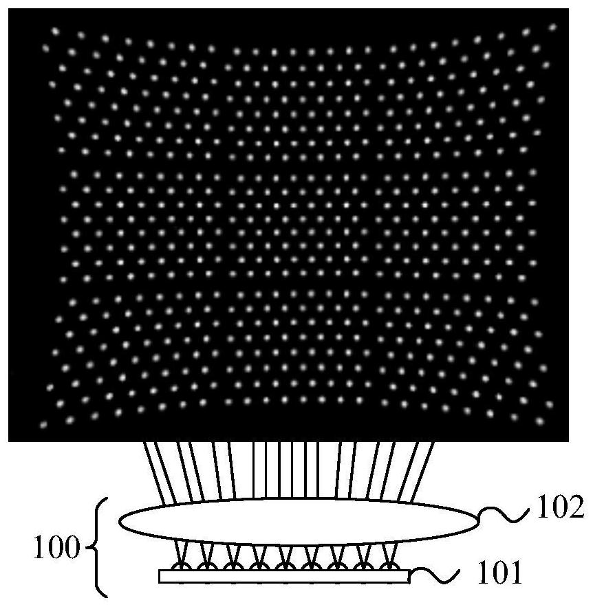
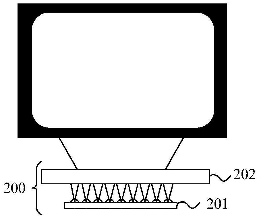
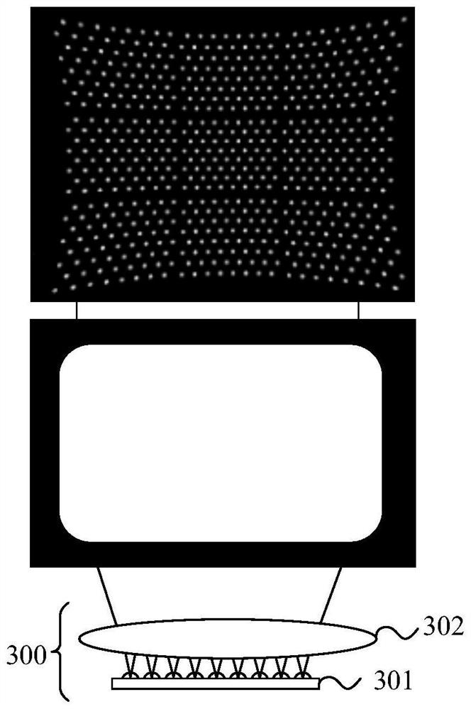
[0048] 3D depth detection is generally divided into: time of flight (TOF), structured light (SL) and binocular stereo vision according to different measurement principles. Among them, the time-of-flight method adopts the active light detection method, and obtains the distance of the target object by detecting the flight (round-trip) time of the optical signal. The time-of-flight depth detection device generally consists of light sources, optical components, sensors, control circuits and processing circuits. According to the continuous state of the signal light in the object plane, the time-of-flight depth detection transmitter can be divided into Flood TOF and Spot TOF.

[0049] like figure 1 and figure 2 As shown, respectively, a Spot TOF deep detection transmitter and a Flood TOF deep detection transmitter according to an embo...


PUM


Abstract

The invention relates to a depth detection transmitting device and electronic equipment. The transmitting device comprises a light source which comprises a light-transmitting array composed of N light-transmitting units and is used for transmitting N beams of light; and a transmitting lens used for collimating the N beams of light, wherein the transmitting lens is used for projecting the N beams of light to a first target object to form a floodlight signal and projecting the N beams of light to a second target object to form a speckle light signal, the distance between the first target object and the transmitting lens is within a first distance, the distance between the second target object and the emission lens is beyond the first distance, and the floodlight signal and the speckle light signal are used for acquiring depth information of the first target object and the second target object. According to the depth detection transmitting device, the special transmitting lens is designed, so that the transmitting device can obtain the depth information of a plurality of target objects within and beyond a certain distance at the same time, two different optical signals can be emitted only through one set of optical path system, and the working efficiency of the depth detection transmitting device is improved.

Description

technical field [0001] The present application relates to the technical field of depth measurement, and more particularly, to a depth detection transmitter, receiver and electronic equipment. Background technique [0002] 3D TOF (Time of flight, TOF), as the current mainstream three-dimensional depth measurement method, obtains the depth information of the target object by measuring the flight time of the signal light in space. The TOF depth detection device consists of a transmitting device and a receiving device. The transmitting device modulates light to form a modulated optical signal on the surface of the target object, and the receiving device receives the depth optical signal carrying depth information returned by the target object, and according to the phase of the two optical signals The depth information of the target object is calculated by parameters such as difference or time difference. As a key component of high-end camera systems, it has been widely used in ...

Claims


Application Information

Patent Timeline
Patent Type & Authority Applications(China)
IPC IPC(8): G01S17/08G01S7/481G01B11/22
CPCG01S17/08G01S7/4811G01B11/22
Inventor 王玉栋
Owner GOODIX TECH (CHENGDU) CO LTD
Features
  • R&D
  • Intellectual Property
  • Life Sciences
  • Materials
  • Tech Scout
  • Unparalleled Data Quality
  • Higher Quality Content
  • 60% Fewer Hallucinations
Learn More