CNC machining center numerical control system
A numerical control system and machining center technology, applied in metal processing equipment, metal processing machinery parts, manufacturing tools, etc., can solve problems such as difficulty in controlling the moving speed of CNC lathes, high quality of CNC lathes, and difficult moving processes, so as to improve control Speed effect, easy to move, and smooth moving speed
- Summary
- Abstract
- Description
- Claims
- Application Information
AI Technical Summary
Problems solved by technology
Method used
Image

Examples
Embodiment 1
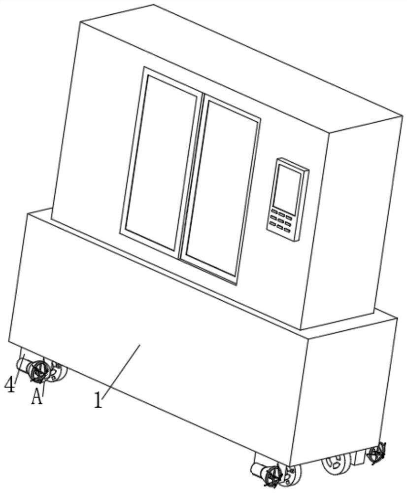
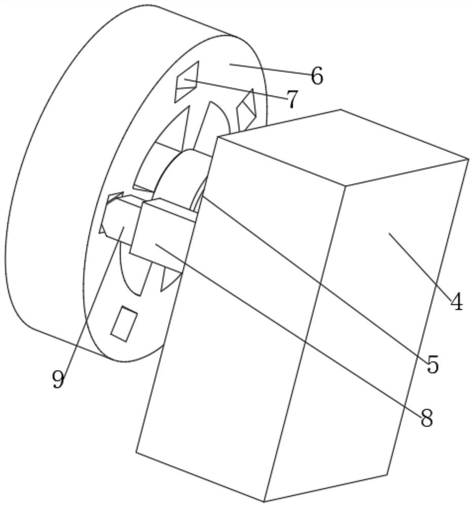
[0032] refer to Figure 1-5 , a CNC machining center numerical control system, including a lathe body 1, two symmetrically distributed legs 4 are fixed on both sides of the bottom of the lathe body 1 by bolts, the inner end surface of the legs 4 is fixed with a sleeve rod 8 by bolts, and the inner end surface of the sleeve rod 8 An embedding groove 10 is provided, the inner wall of the front end of the embedding groove 10 is fixed with two symmetrically distributed first springs 11 by bolts, the rear ends of the two first springs 11 are fixed with the same inner rod 9 by bolts, and the end section of the inner rod 9 is Set in a triangle, the inner end surface of the leg 4 is connected to the connecting shaft 5 through bearing rotation, the rear end of the connecting shaft 5 is fixed with a roller 6 by bolts, the front end of the roller 6 is provided with a plurality of slots 7 distributed in an annular array, and the front end of the inner rod 9 is glued. A permanent magnet 12...
Embodiment 2
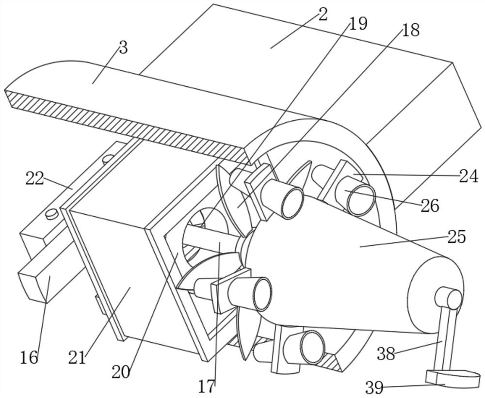
[0040] refer to Figure 6-8 , a CNC machining center numerical control system, the outer side of the cover tube 23 is welded with a ring plate 27, the ring plate 27 is fixed with a bracket 28 by bolts, one side of the bracket 28 is penetrated with an opening 29, and a movable rod 30 is arranged in the opening 29, The outer side of the movable rod 30 is fixed with a column 31 by a bolt, the column 31 is sleeved and fixed with a collar 32, the outer side of the collar 32 is fixed with a plurality of first groove blocks 33 distributed in an annular array by bolts, and the outer side of the ring plate 27 is fixed by a bolt. A plurality of second slot blocks 34 distributed in an annular array are fixed, and the same stop rod 36 is arranged between the first slot block 33 and the second slot block 34, and the stop bar 36 and the first slot block 33 are rotationally connected by bearings .
[0041] Further, the inner walls of both ends of the second groove block 34 are fixed with mo...
PUM
 Abstract
Description
Claims
Application Information
 - R&D
- Intellectual Property
- Life Sciences
- Materials
- Tech Scout
- Unparalleled Data Quality
- Higher Quality Content
- 60% Fewer Hallucinations
Browse by: Latest US Patents, China's latest patents, Technical Efficacy Thesaurus, Application Domain, Technology Topic, Popular Technical Reports.
© 2025 PatSnap. All rights reserved.Legal|Privacy policy|Modern Slavery Act Transparency Statement|Sitemap|About US| Contact US: help@patsnap.com