Lightweight integrated bearing main shaft unit

A spindle and bearing technology, applied in the field of lightweight integrated bearing spindle unit, can solve the problems of large bearing assembly error, poor bearing protection, low bearing life, etc., reduce the axial and radial dimensions and overall weight, and reduce the cost of use , Reduce the effect of axial movement

Pending Publication Date: 2022-02-08
QINGDAO TAIDE AUTOMOBILE BEARING
View PDF0 Cites 0 Cited by
  • Summary
  • Abstract
  • Description
  • Claims
  • Application Information

AI Technical Summary

Problems solved by technology

However, the center distance between the power heads is very small, and the conventional spindle unit is used. Due to the size limitation, only a small-volume spindle unit can be used. In this case, the rigidity of the spindle, the bearing capacity of the bearing, and the power transmission capacity are very low Limited, only some small size processing and finishing can be carried out, and cannot meet the processing requirements of high load, high efficiency and large size
[0004] There is also a plan to install multiple spindles on the housing. The bearings are installed on the housing, which requires high processing requirements for the housing, poor bearing protection, large assembly errors of the front and rear bearings, and tolerances and radial clearances between the bearings. In the assembly process, the bearing needs to be finely adjusted, and it is difficult to make the working accuracy and life of the bearing consistent
Due to protection problems during use, the bearing life is very low and the failure rate of the machine tool is high

Method used


Image

  • Lightweight integrated bearing main shaft unit
  • Lightweight integrated bearing main shaft unit
  • Lightweight integrated bearing main shaft unit

Examples


Embodiment Construction

[0032] The technical solutions in the embodiments of the present invention will be clearly and completely described below in conjunction with the accompanying drawings. Apparently, the described embodiments are only part of the embodiments of the present invention, not all of them. Based on the embodiments of the present invention, all other embodiments obtained by persons of ordinary skill in the art without making creative efforts belong to the protection scope of the present invention.

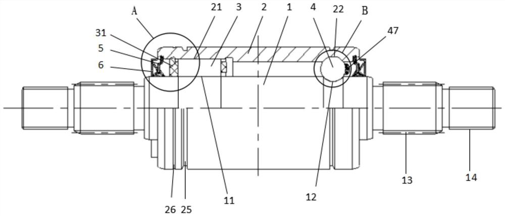
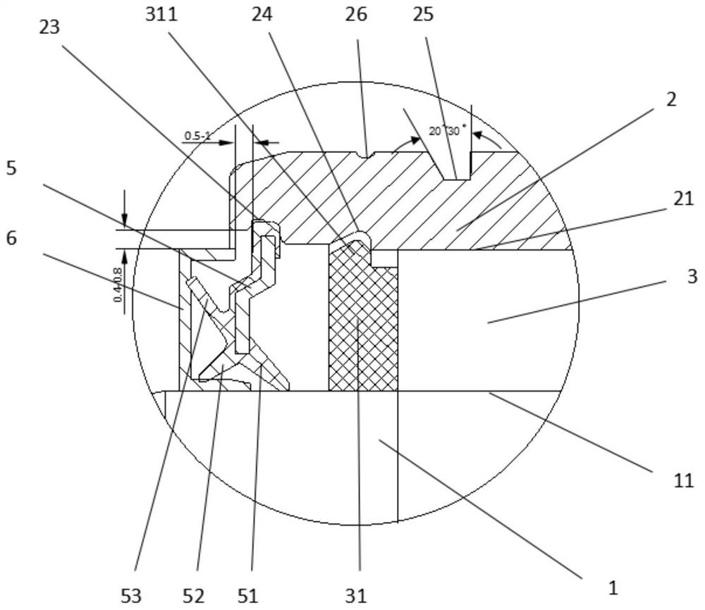
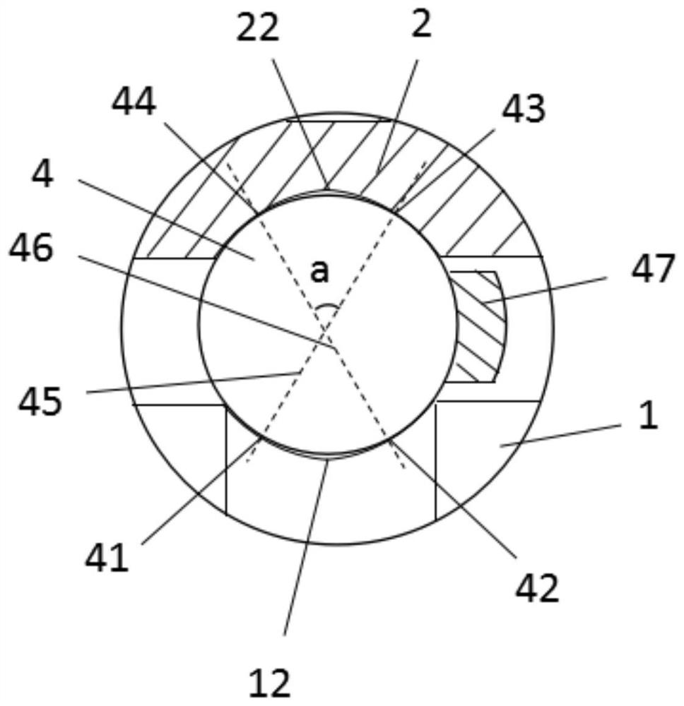
[0033] A light-weight integrated bearing spindle unit, refer to Figure 1 to Figure 3 As shown, including the main shaft 1, one end of the main shaft 1 is the load input end, and the other end is the load output end. 3 and a row of steel balls 4, the main shaft 1 is provided with a main shaft linear raceway 11 and a main shaft arc groove 12 along the outer diameter, wherein the main shaft linear raceway 11 is close to the load output end of the main shaft 1, and the main shaft arc groove 12...


PUM


Abstract

The invention relates to a lightweight integrated bearing main shaft unit. The lightweight integrated bearing main shaft unit comprises a main shaft with a load input end and a load output end, the main shaft is sleeved with an integrated outer ring, a row of cylindrical rollers and a row of steel balls are arranged between the main shaft and the inner wall of the integrated outer ring, a linear raceway and an arc channel are respectively arranged at the corresponding positions of the inner walls of the main shaft and the integrated outer ring, the linear raceway is close to the load output end, the arc channel is close to the load input end, the cylindrical rollers roll in the linear raceway, the steel balls roll in the arc channel, the steel balls are in four-point contact with the arc channel, sealing rings are arranged between the two ends of the inner diameter of the integrated outer ring and the outer diameter surface of the main shaft, a limiting groove is formed in the inner wall of the integrated outer ring to limit a cylindrical roller retainer, and a stop groove or a flange is arranged on the outer diameter of the integrated outer ring. The lightweight integrated bearing main shaft unit is compact in structure; and the axial and radial sizes and the overall weight of the main shaft unit are reduced. The lightweight integrated bearing main shaft unit has the advantages of small axial movement, good rigidity, high precision, convenience in installation and use, lower cost and the like.

Description

technical field [0001] The invention belongs to the technical field of finished main shaft unit structure for industrial equipment, and in particular relates to a lightweight integrated bearing main shaft unit. Background technique [0002] The main shaft is widely used as a mechanical power transmission structure, such as in machine tools, mechanical transmission, sports equipment, etc. The finished spindle unit is mainly composed of the main shaft, the bearings installed at both ends of the main shaft, and the housing installed on the outer diameter of the bearing, and there are also some auxiliary parts, such as end covers on both sides of the bearing, internal or external end covers to prevent contamination and lubrication The oil seal for oil leakage, the spring for preloading the bearing, the grease filled inside the main shaft for bearing lubrication, the adjusting gasket between the end covers, etc. Adding and subtracting spacers between them solves the axial serial...

Claims


Application Information

Patent Timeline
Patent Type & Authority Applications(China)
IPC IPC(8): F16C19/49F16C33/58F16C33/80F16C33/78F16C33/46F16C33/38
CPCF16C19/49F16C33/583F16C33/80F16C33/7823F16C33/46F16C33/38Y02T10/86
Inventor 陈升儒郭延伟赵国庆
Owner QINGDAO TAIDE AUTOMOBILE BEARING
Why Eureka
Try Eureka