
Eureka
For R&D, Eureka makes reading and utilizing patents & technical documents easy.
Eureka AIR
Designed for self-driven R&D workflows. Generate viable solutions, solve complex R&D challenges, empower your innovation with AI.

Eureka Materials
Designed for material experts only. Revolutionize your material R&D, from search, analyze, to developing new materials.

TechResearch
Generate reliable direction feasibility study reports for your R&D in just a few steps.

TechSeek
Discover and master advanced knowledge NOW. Basics, ideas, possibilities, all at once.

TechMind
As an expert in R&D Theories, TechMind can generates customized viable solutions instantly.

TechRisk
Analyze your overall solution with one click, know your potential R&D risks in advance.

TechMonitor
Get weekly tech updates, stay abreast of the latest tech innovations and key insights.
Integrated sludge pulping and hydrolyzing equipment
A treatment equipment, sludge slurry technology, applied in sludge treatment, water/sludge/sewage treatment, sludge treatment through temperature control, etc., which can solve the problem of high overall system energy consumption, high investment and large footprint and other problems, to achieve the effect of overall compact system, low failure rate and simple control.
- Summary
- Abstract
- Description
- Claims
- Application Information
AI Technical Summary
Problems solved by technology
Method used
Image

Examples
Embodiment 1
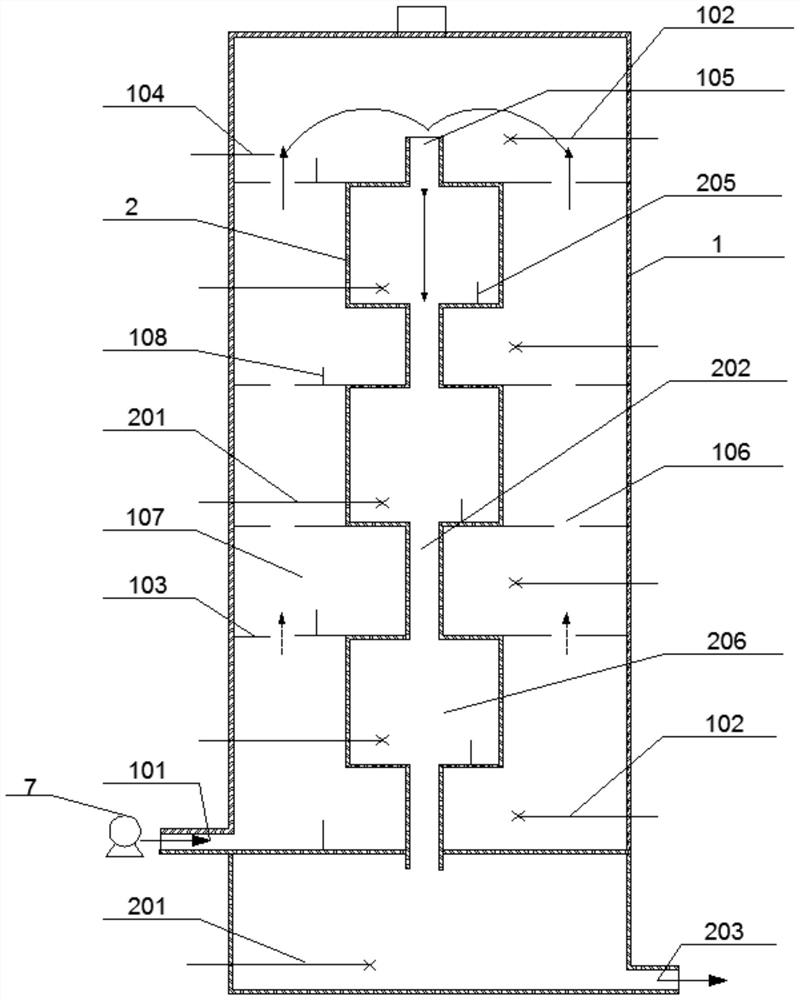
[0054] Embodiment 1: as Figure 1-Figure 4 As shown, a kind of sludge slurry hydrolysis integrated treatment equipment of the present invention comprises:
[0055] A cold sludge chamber 1, the cold sludge chamber 1 is used to import cold sludge to be treated; the cold sludge includes municipal sludge and other organic sludge;
[0056] The hot sludge chamber 2, the sludge treated by the cold sludge chamber 1 enters the hot sludge chamber 2;
[0057] A sleeve-shaped wrapping structure is adopted between the cold sludge chamber 1 and the hot sludge chamber 2, and the cold sludge chamber 1 and the hot sludge chamber 2 perform heat exchange to complete slurrying and hydrolysis treatment of sludge.
[0058] In this embodiment, the cold sludge chamber 1 is wrapped on the outside of the hot sludge chamber 2 . The cold sludge to be treated is sent into the cold sludge chamber 1, and the sludge sent from the cold sludge chamber 1 is sent into the hot sludge chamber 2. The hot sludge ch...
Embodiment 2
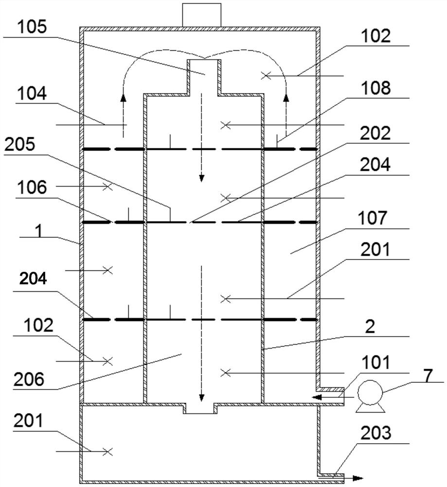
[0089] Embodiment 2: as Figure 5-Figure 8 As shown, the difference from Example 1 is that in this example, the hot sludge chamber 2 is wrapped on the outside of the cold sludge chamber 1 . The cold sludge to be treated is sent into the cold sludge chamber 1, and the sludge sent from the cold sludge chamber 1 is sent into the hot sludge chamber 2. The hot sludge chamber 2 is used for heat exchange with the cold sludge chamber 1, that is, the cold sludge chamber 1 will absorb the heat of the wrapped hot sludge chamber 2; while the hot sludge in the hot sludge chamber 2 is gradually cooled After the sludge chamber 1 absorbs heat, it can be lowered to the appropriate temperature required by the back-end process, reducing the cooling mechanism in the traditional processing equipment, which not only improves the overall efficiency of the system but also reduces the energy consumption of the system.
[0090] In this example, the hot sludge chamber 2 and the cold sludge chamber 1 ca...
Embodiment 3
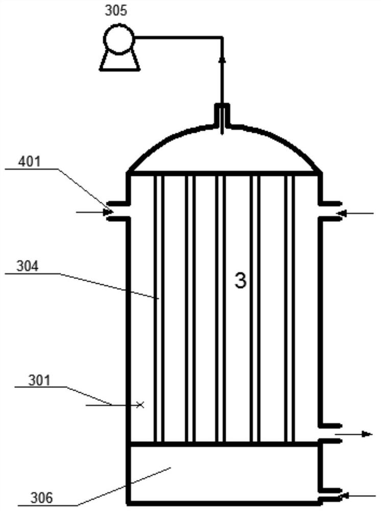
[0098] Embodiment 3: as Figure 9-Figure 11 As shown, in this example, the structure in which the hot sludge chamber 2 wraps the cold sludge chamber 1 is also adopted, and its basic structure and process route are basically the same as those in Example 2, except that: the vertically arranged from top to bottom The middle part of the cold sludge chamber 1 is pierced with several communicating pipes, which are only used to allow the sludge in the hot sludge chamber 2 to pass through, but will not mix with the sludge in the cold sludge chamber 1 . In the present invention, an internal circulation agitation device is further provided at the position corresponding to the communication pipe in the hot sludge chamber 2, and the heat circulation agitation device can generate suction or propulsion effects to complete the flow of hot sludge in the communication pipe. In this way, the heat exchange capacity can be greatly enhanced, the uniform heat effect of the heat exchange can be impr...
PUM
 Abstract
Description
Claims
Application Information
 - R&D Engineer
- R&D Manager
- IP Professional
- Industry Leading Data Capabilities
- Powerful AI technology
- Patent DNA Extraction
Browse by: Latest US Patents, China's latest patents, Technical Efficacy Thesaurus, Application Domain, Technology Topic, Popular Technical Reports.
© 2024 PatSnap. All rights reserved.Legal|Privacy policy|Modern Slavery Act Transparency Statement|Sitemap|About US| Contact US: help@patsnap.com