Feeding device with variable-pitch clamping jaws

A gripper and double gripper technology, applied in the field of automatic feeding equipment, can solve the problems of increased design cost, inability to carry heavy objects, and low work efficiency, to meet the requirements of the work space, increase mechanical strength, and reduce production costs Effect

Pending Publication Date: 2022-02-11
合肥双合智能科技有限公司
View PDF13 Cites 0 Cited by
  • Summary
  • Abstract
  • Description
  • Claims
  • Application Information

AI Technical Summary

Problems solved by technology

[0004] In the prior art, the motor stator is mostly loaded by a single conveyor, and the motor stator in the tray is directly moved to the assembly station by manual or six-axis manipulator. This type of feeding method requires the staff to move the materials in the tray Replenish to the pick-up position in time, low work efficiency
[0005] Among them, in automation equipment, the application of the jaw mechanism is relatively mature, and the jaw mechanism is mainly used for grasping and moving the workpiece; however, most of the jaw grippers currently use a single jaw to grasp the workpiece. low work efficiency
[0006] In order to improve work efficiency, some grippers in the prior art also contain two jaws, but the two jaws in this gripper are connected to the manipulator in a fixed connection mode, and the position between the two jaws is relatively fixed. , on the one hand, it cannot be adjusted according to the distance between the workpieces to be grasped; on the other hand, when the distance between the two workpieces in the previous process is inconsistent with the distance between the two workpieces in the next process, the gripper cannot complete the work Task
[0007] In addition, for the convenience of design and assembly, most of the three-axis manipulators in the prior art are directly driven by the servo slide module; however, the mechanical strength of the servo slide module is not enough to carry heavy objects. Requirements, you need to choose a large-size servo slide module, on the one hand, it cannot meet the requirements of the work space, on the other hand, it increases the design cost, cannot control the design cost of the entire equipment within the budget, and cannot meet customer needs
[0008] In view of the above-mentioned problems, the feeding mechanism in the prior art cannot well meet the needs of the workshop to realize automatic production, and further improvement is needed

Method used


Image

  • Feeding device with variable-pitch clamping jaws
  • Feeding device with variable-pitch clamping jaws
  • Feeding device with variable-pitch clamping jaws

Examples


Embodiment Construction

[0039] It should be noted that, in the case of no conflict, the embodiments in the present application and the features in the embodiments can be combined with each other. The present invention will be described in detail below with reference to the accompanying drawings and examples.

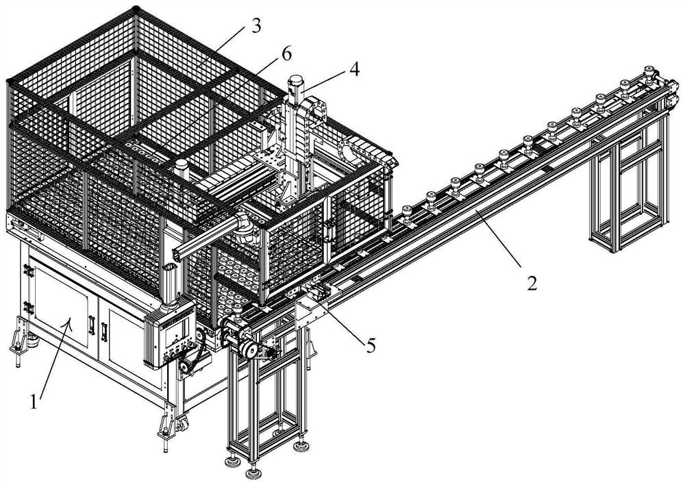
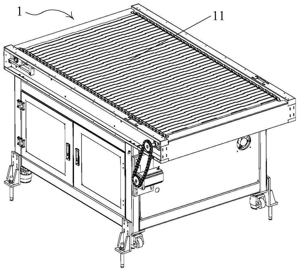
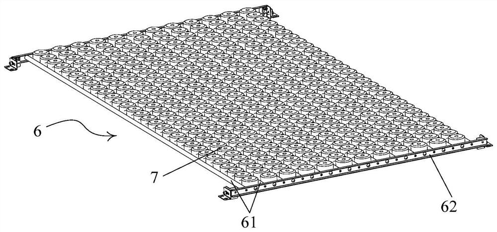
[0040] like Figure 1 to Figure 9 As shown, the feeding device with variable-pitch jaws of the present invention includes a plate chain conveyor 1, a chain conveyor 2, a protective cover 3, a three-axis manipulator 4, a positioning tool 5, and a storage frame 6.

[0041] The storage frame 6 is set on the upper end of the plate chain conveyor 1, and a large number of grasped workpieces are regularly placed inside it. The chain conveyor 2 is located on the side of the plate chain conveyor 1, and the three-axis manipulator 4 is set above the plate chain conveyor 1. , the three-axis manipulator 4 is used to grab the workpiece, place it on the workpiece placement tooling 21 of the chain conveyor 2,...


PUM


Abstract

The invention discloses a feeding device with variable-pitch clamping jaws. The feeding device comprises a plate chain conveyor, a chain conveyor, a protective cover, a three-axis mechanical arm and a storage frame; the three-axis mechanical arm is provided with a double-clamping-jaw picker, the double-clamping-jaw picker is provided with a linear air cylinder and a pair of air claw air cylinders used for grabbing two workpieces at the same time, and when the linear air cylinder works, the distance between the two air claw air cylinders can be changed so as to meet the feeding requirement that the distance between the two workpieces before and after picking is not consistent. By means of the plate chain conveyor, the workpieces are always arranged at the foremost end of the storage frame, and the situation that the three-axis mechanical arm grabs nothing can be avoided; the double-clamping-jaw picker is arranged, the linear air cylinder is used for driving the double-clamping-jaw picker, the two workpieces with different distances can be grabbed, so that the feeding device is suitable for the situation that the distance between the two workpieces during grabbing is inconsistent with the distance between the two workpieces during placing; and by means of a positioning tool, the three-axis mechanical arm can conveniently place the workpieces on the positioning tool, the accuracy is improved, and the requirement of a robot for achieving automatic production is well met.

Description

technical field [0001] The invention relates to the field of automatic feeding equipment, in particular to a feeding device with variable-distance jaws. Background technique [0002] As the stationary part of the motor rotation, the stator of the motor realizes the normal operation of the motor by cooperating with the rotor of the motor. The general stator is composed of the stator core, the stator winding and the machine base. The stator mainly relies on the rotation when the motor works. To generate a magnetic field, the more common stators on the market are generally divided into centralized and distributed, which are basically distinguished by the shape of the coil and the wiring method of the mosaic. In view of the different power outputs of different motors, it is necessary to assemble motors of different specifications Different stators and rotors. [0003] In the current market, in order to realize the high-yield production of motor stators, most of the processing i...

Claims


Application Information

Patent Timeline
IPC IPC(8): B65G47/91B65G17/12B65G47/74
CPCB65G47/918B65G47/912B65G17/12B65G47/74
Inventor 李恝秦仲琪
Owner 合肥双合智能科技有限公司
Why Eureka
Try Eureka