Rapid drilling rig for solid mineral exploration

A mineral and fast technology, applied in the field of fast drilling devices for solid mineral exploration, can solve the problems of insufficient fixation, insufficient fixation effect, waste of resources, etc.

Inactive Publication Date: 2022-02-18
王盼盼
View PDF1 Cites 0 Cited by
  • Summary
  • Abstract
  • Description
  • Claims
  • Application Information

AI Technical Summary

Problems solved by technology

[0005] The insertion and fixing of the outriggers in the above-mentioned drilling device is realized by another driving device, which not only wastes resources, but also requires an additional motor, and its fixing effect is not good enough. The resistance increases, and the directly inserted outriggers are likely to be jacked up, resulting in insufficient fixation;

Method used


Image

  • Rapid drilling rig for solid mineral exploration
  • Rapid drilling rig for solid mineral exploration
  • Rapid drilling rig for solid mineral exploration

Examples


Embodiment 1

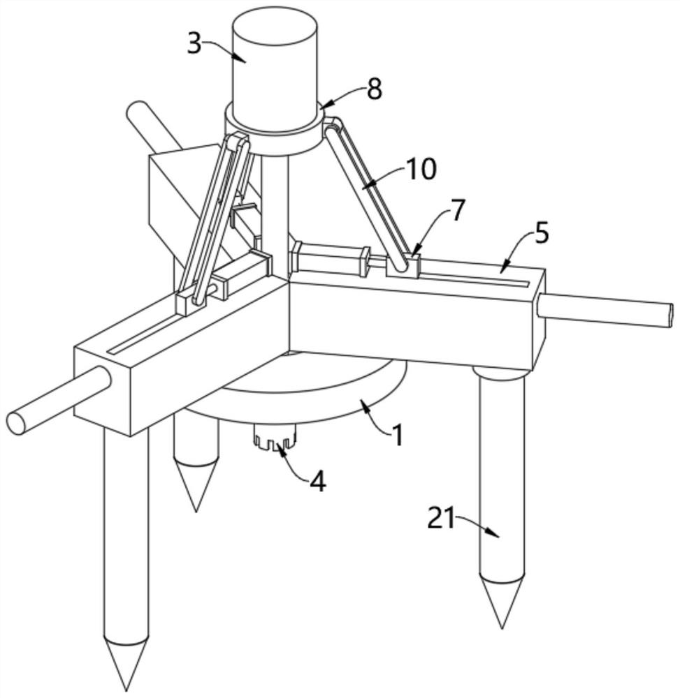
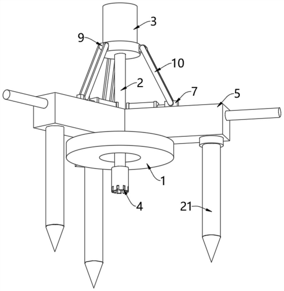
[0046] see figure 1 and figure 2 , a fast drilling device for solid mineral exploration, comprising a mounting ring 1, a drill rod 2 is arranged to rotate inside the mounting ring 1, the drill rod 2 is fixedly mounted on the bottom of the output shaft of a driving motor 3, and a drill bit is fixedly mounted on the bottom of the drill rod 2 4. Several fixed cabinets 5 are evenly arranged on the top of the installation ring 1, and several fixed cabinets 5 are arranged around the drill pipe 2. The tops of several fixed cabinets 5 close to the end of the drill pipe 2 are all fixedly installed with electric push rods 6, and the electric push rods A movable block 7 is fixedly installed on the top of the output shaft of the rod 6. In this embodiment, there are three fixed cabinets 5, electric push rods 6 and movable blocks 7;

[0047] The bottom of the drive motor 3 is fixedly installed with a mounting plate 8, and the edge of the mounting plate 8 is provided with a number of conne...

Embodiment 2

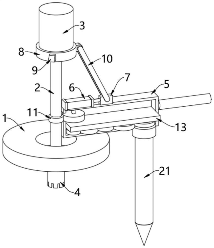
[0050] see Figure 3-Figure 5 , on the basis of Embodiment 1, the insides of several fixed cabinets 5 are all formed with inner chambers 12, and the insides of several inner chambers 12 are all horizontally provided with partitions 13, and partitions 13 divide the inner chambers 12 into upper control chambers and the lower drive chamber, the bottom of several fixed cabinets 5 is provided with bearings 22 at the end away from the drill pipe 2, and the inner walls of several bearings 22 are fixedly equipped with struts 21, which are arranged in the linkage between the drill pipe 2 and the struts 21. The mechanism is used to synchronously drive the support rod 21 to rotate when the drill rod 2 is at a preset position and is driven by the drive motor 3 to rotate. In this embodiment, specifically:

[0051] The linkage mechanism comprises a driving wheel 11, a first gear 14, a vertical shaft 15, a second gear 16, a third gear 17, a fourth gear 18, a fifth gear 19 and a driven wheel ...

Embodiment 3

[0055] see Figure 6-Figure 10 , on the basis of Embodiment 1 or Embodiment 2, handles 23 are fixedly installed on the ends of several fixed cabinets 5 away from the drill pipe 2, and the fixed cabinets 5 and the installation ring 1 are conveniently lifted through the handles 23, which is more convenient to use , and easy to carry;

[0056] The inside of the pole 21 is provided with two push plates 29 opposite to each other, and the opposite side of the two push plates 29 is provided with an insertion rod 30, which is inserted into the slot 31, and the slot 31 is opened on the pole 21. On the outer wall of the two push plates 29, when the two push plates 29 are far away from each other, the insertion rod 30 provided on the opposite side will protrude through the slot 31, so as to be inserted horizontally into the ground, and the insertion rod 30 can be inserted laterally into the ground to increase the size of the pole. The grasping force between 21 and the ground makes the i...


PUM


Abstract

The invention relates to the technical field of mineral exploration, and discloses a quick drilling rig for solid mineral exploration, which comprises a mounting ring, a drill rod is rotatably arranged in the mounting ring, the drill rod is fixedly mounted at the bottom of an output shaft of a driving motor, a drill bit is fixedly mounted at the bottom of the drill rod, a plurality of fixed cabinets are uniformly arranged at the top of the mounting ring, the plurality of fixed cabinets are arranged around the drill rod, and electric push rods are fixedly mounted at the ends, close to the drill rod, of the tops of the plurality of fixed cabinets; a movable block at the top of an output shaft of the electric push rod is movably connected with the connecting block through a hinge rod, the output shaft of the electric push rod extends out to drive the movable block to move, the movable block moves to pull the connecting block and the mounting plate to move downwards through the hinge rod, and the mounting plate moves downwards to drive a driving motor to move downwards. The driving motor moves downwards to drive the drill rod at the bottom of the output shaft to move downwards, the height of the drill rod is adjusted, and drilling on the ground is facilitated.

Description

technical field [0001] The invention relates to the technical field of mineral exploration, in particular to a fast drilling device for solid mineral exploration. Background technique [0002] Solid minerals refer to the solid natural enrichment of real economic significance or potential economic significance formed by geological processes on the surface or in the earth's crust, including coal, oil shale, stone coal, natural bitumen, uranium, thorium, etc. in energy minerals All metallic minerals and most of non-metallic minerals; in the exploration of solid minerals, in order to determine the solid minerals on the surface, the solid mineral area is generally drilled; [0003] The Chinese patent announcement number is: the invention patent of CN112324355A, which provides a drilling device and drilling process for geotechnical engineering investigation, which relates to the technical field of geotechnical engineering investigation, wherein the drilling device includes a frame...

Claims


Application Information

Patent Timeline
Patent Type & Authority Applications(China)
IPC IPC(8): E21B3/02E21B15/00
CPCE21B3/02E21B15/006
Inventor 王盼盼李磊
Owner 王盼盼
Why Eureka
Try Eureka