
Miniaturized non-contact waveguide transmission line and application

A waveguide transmission line, non-contact technology, applied in the direction of waveguide, waveguide-type devices, circuits, etc., can solve the problems of passive intermodulation interference, affecting the performance of circuit components and systems, and increasing the size of waveguide, so as to reduce surface treatment process and Assembly process requirements, realize small compactness and light weight, and reduce the effect of lateral size

Active Publication Date: 2022-02-18
XIDIAN UNIV
View PDF6 Cites 1 Cited by
  • Summary
  • Abstract
  • Description
  • Claims
  • Application Information

AI Technical Summary

Problems solved by technology

Based on this, the traditional waveguide transmission line has the following problems in practical application: integrated processing is difficult to meet the manufacturing requirements of complex circuit components; Many problems caused, such as increased loss, passive intermodulation interference caused by contact nonlinearity, etc., affect actual circuit components and system performance
[0005](1) When the traditional waveguide transmission line is applied in actual circuit components, it is easy to produce bad metal electrical contact effect, which will lead to increased loss, increased manufacturing process cost, and design flexibility Reduced, etc., and prone to passive intermodulation interference problems
[0006](2) Existing non-contact waveguide transmission lines have the problem of excessive lateral dimensions, which is not conducive to the miniaturization and weight reduction of circuits, components and systems
[0007]The difficulty in solving the above problems and defects is: limited by the actual waveguide structure and the principle of electromagnetic bandgap, when realizing a non-contact waveguide transmission line, the non-contact electromagnetic bandgap structure will Occupies additional space, resulting in increased waveguide size

Method used


Image

  • Miniaturized non-contact waveguide transmission line and application
  • Miniaturized non-contact waveguide transmission line and application
  • Miniaturized non-contact waveguide transmission line and application

Examples


Embodiment 1

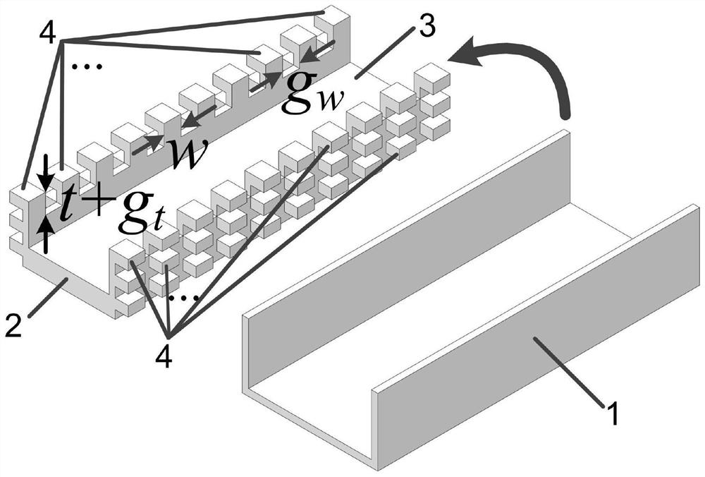
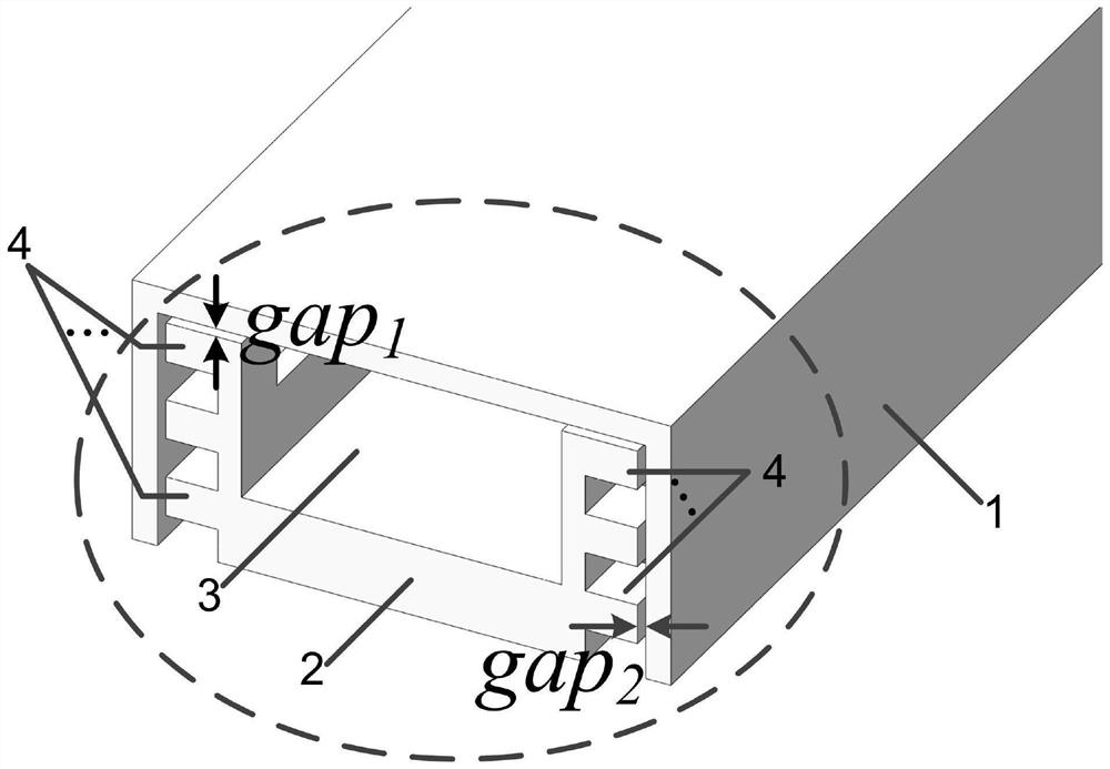
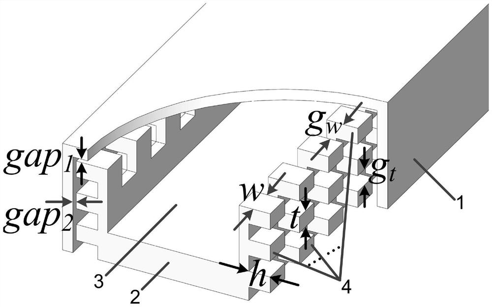
[0070] like Figure 1 - Figure 3 As shown, the miniaturized non-contact waveguide transmission line provided by the present invention includes at least a waveguide upper cover 1 and a waveguide substrate 2, wherein the waveguide upper cover 1 is a rectangular groove-shaped structure, the length of the groove is equal to the length, groove of the waveguide base 2. The width is greater than or equal to the width of the waveguide base 2, the groove depth is greater than or equal to the height of the waveguide substrate 2; the waveguide base 2 includes a waveguide groove 3 and a periodic metal protrusion array 4. The periodic metal protrusion array 4 includes several highly identical rectangular columnar metal protrusions, uniformly disposed of a rush of a row, uniformly disposed on both sides of the waveguide groove 3; the waveguide upper cover 1 is nested on the waveguide matrix 2, waveguide The upper surface of the inner wall of the cover 1 is between the surface of the side wall of...

Embodiment 2

[0093] Structure Figure 9 As shown, a miniaturized non-contact waveguide transmission line includes at least the waveguide upper cover 1 and the waveguide base 2, the waveguide upper cover 1 is a rectangular groove-shaped structure, the length of the groove is equal to the length of the waveguide base 2, and the groove width is greater than or equal to. The width of the waveguide base 2, the groove depth is greater than or equal to the height of the waveguide base 2; the waveguide base 2 includes a waveguide groove 3 and a periodic metal protrusion array 4. The periodic metal protrusion array 4 includes several highly identical rectangular columnar metal protrusions, uniformly disposed of a rush of a row, uniformly disposed on both sides of the waveguide groove 3; the waveguide upper cover 1 is nested on the waveguide matrix 2, waveguide The upper surface of the inner wall of the cover 1 is between the surface of the side wall of the waveguide groove 3 presents a gap GAP 1 , There...

Embodiment 3

[0096] Structure Figure 11 As shown, a miniaturized non-contact waveguide transmission line includes at least the waveguide upper cover 1 and the waveguide base 2, the waveguide upper cover 1 is a rectangular groove-shaped structure, the length of the groove is equal to the length of the waveguide base 2, and the groove width is greater than or equal to. The width of the waveguide base 2, the groove depth is greater than or equal to the height of the waveguide base 2; the waveguide base 2 includes a waveguide groove 3 and a periodic metal protrusion array 4. The periodic metal protrusion array 4 includes several highly identical rectangular columnar metal protrusions, uniformly disposed of a rush of a row, uniformly disposed on both sides of the waveguide groove 3; the waveguide upper cover 1 is nested on the waveguide matrix 2, waveguide The upper surface of the inner wall of the cover 1 is between the surface of the side wall of the waveguide groove 3 presents a gap GAP 1 , Ther...


PUM


Abstract

The invention belongs to the technical field of electromagnetic fields and microwaves, and discloses a miniaturized non-contact waveguide transmission line and application thereof. The miniaturized non-contact waveguide transmission line comprises a waveguide upper cover and a waveguide base body, the waveguide base body is formed by arranging periodic metal convex body arrays on the outer walls of the two sides of a waveguide groove, and the waveguide upper cover is of a groove-shaped structure and is nested on the waveguide base body; gaps exist between the inner surface of the waveguide upper cover and all opposite faces of the waveguide base body, the metal convex body arrays and the opposite metal faces form electromagnetic band gaps, and the electromagnetic shielding of waveguide transmission signals is achieved. Compared with a traditional waveguide transmission line, the non-contact waveguide transmission line has the advantages that broadband single-mode transmission performance is achieved, meanwhile, a non-contact structure is achieved, many problems caused by poor metal electric contact can be effectively avoided, the surface treatment and assembly process requirements are greatly reduced, and higher design flexibility is achieved. According to the invention, the transverse size is greatly reduced, which is more beneficial for realizing small size and light weight of microwave and millimeter wave circuits, components and systems.

Description

Technical field [0001] The present invention belongs to the field of electromagnetic fields and microwave technologies, and more particularly to a miniaturized non-contact waveguide transmission line and application. Background technique [0002] At present, the waveguide transmission line is one of the most widely used transmission lines in the microwave millimeter wave circuit and the system, and is the basis for constituting various microwave millimeter wave circuits, components and systems. Traditional waveguides typically use the manufacturing method of reloading after integrated processing or split processing; for waveguide components, integrated processing is difficult, typically machined, and then electrically processed and then connected by welding or screw As a one. Based on this, traditional waveguide transmission lines have the following problems in practical applications: integrated processing is difficult to meet the manufacture of complex circuit components; Many p...

Claims


Application Information

Patent Timeline
Patent Type & Authority Applications(China)
IPC IPC(8): H01P3/10H01P3/12
CPCH01P3/10H01P3/12
Inventor 陈翔孙冬全王小丽崔万照李小军
Owner XIDIAN UNIV
Learn More