Airtight waveguide-microstrip transition structure

A transition structure and waveguide technology, applied in the microwave field, can solve problems such as the inability to guarantee the air tightness of the waveguide and the components, and achieve the effect of avoiding signal leakage and ensuring electrical performance.

Active Publication Date: 2022-02-18
航天科工微系统技术有限公司
View PDF8 Cites 0 Cited by
  • Summary
  • Abstract
  • Description
  • Claims
  • Application Information

AI Technical Summary

Problems solved by technology

[0006] In line with the current development of microwave technology, the waveguide-microstrip transition is also developing in the direction of miniaturization, airtightness, low power consumption, and easy production. At present, the mature structural forms for realizing the transition from waveguide to microstrip mainly include: waveguide-antipolar Fin line-microstrip transition, waveguide-ridge waveguide-microstrip transition, waveguide-probe-microstrip transition, etc., but none of the above transition structures can guarantee the airtightness of the waveguide and the inside of the component

Method used


Image

  • Airtight waveguide-microstrip transition structure
  • Airtight waveguide-microstrip transition structure
  • Airtight waveguide-microstrip transition structure

Examples


Embodiment 1

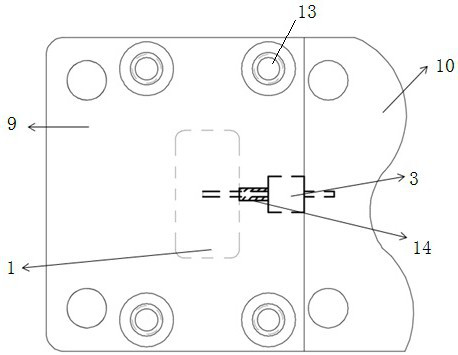
[0037] Such as Figure 1-4 As shown, the airtight waveguide-microstrip transition structure disclosed in this implementation includes a waveguide cavity 1 and an airtight cavity 2 for installing a microstrip circuit. The waveguide cavity 1 and the microstrip circuit are electrically connected through glass beads 3 . specific:

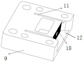
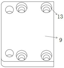
[0038] The waveguide cavity 1 includes an upper cavity 9 and a lower cavity 10, the bottom of the upper cavity 9 is open, the top of the lower cavity 10 is open, the bottom of the upper cavity 9 is attached to the top of the lower cavity 10, and the lower cavity 10 The side wall of the glass bead 3 is connected to the side wall of the airtight cavity 2, and the glass bead 3 is located between the upper cavity 9 and the airtight cavity 2, and one end of the pin of the glass bead 3 passes through the side wall of the upper cavity 9, and the pin The other end passes through the side wall of the airtight chamber 2 .

[0039] As a preferred matching method...

Embodiment 2

[0042] Such as Figure 5 As shown, in this embodiment, on the basis of Embodiment 1, in order to avoid the influence of the existence of the air cavity on the performance of the waveguide-microstrip transition structure, when designing the pin hole of the glass bead 3, its diameter should be 50Ω Impedance matching design, therefore, the air cavity 14 here will not affect the transition structure.

Embodiment 3

[0044] Such as Figure 6 , Figure 7 As shown, on the basis of Embodiments 1 and 2, the lower cavity 10 of this embodiment is manufactured integrally with the airtight chamber 2 and processed separately as part A15. The bottom of the airtight chamber 2 is provided with a window, and the window is provided with a cover plate 8; Process the upper cavity 9 as part B.

[0045] When the present invention is assembled, the glass bead 2 is first sintered into the prefabricated glass bead mounting hole of the part A, and then the part B is fixed on the part A with screws; since the inner conductor of the glass bead 3 needs to enter the inside of the waveguide, as The probe is used to receive the signal transmitted by the waveguide port, so the two parts that make up the waveguide cannot be assembled from the vertical direction, but can only be assembled from the horizontal direction.

[0046] In order to ensure the accuracy of assembly and eliminate the errors caused by assembly, two ...


PUM


Abstract

The invention discloses an airtight waveguide-microstrip transition structure. The transition structure comprises a waveguide cavity and an airtight cavity used for installing a microstrip circuit, wherein the waveguide cavity is electrically connected with the microstrip circuit through a glass bead. The transition structure is advantaged in that transition between the waveguide and the internal circuit is achieved through the glass beads, the glass beads are sintered into the waveguide cavity, air tightness from the waveguide cavity to the internal microwave circuit can be guaranteed, and therefore a bare chip in the microwave circuit is effectively protected.

Description

technical field [0001] The invention relates to the field of microwave technology, in particular to an airtight waveguide-microstrip transition structure. Background technique [0002] With the development of miniaturization and modularization of radio frequency microsystems, the integration of various systems is getting higher and higher. As a radio frequency transmission line with simple structure and small size, microstrip line is widely used in it. However, in the long-distance transmission system, due to the limitation of power and loss, compared with the microstrip line, the rectangular waveguide has larger power capacity, less loss, and no radiation loss, so the rectangular waveguide replaces the function of the microstrip line . At the same time, in order to meet the low-loss requirements of high-frequency and high-power applications (such as power amplifier components), the method of using connectors as radio frequency interfaces is no longer applicable. Therefore,...

Claims


Application Information

Patent Timeline
Patent Type & Authority Applications(China)
IPC IPC(8): H01P5/107
CPCH01P5/107
Inventor 田孝园康育贵张霖狄隽周卫袁光辉
Owner 航天科工微系统技术有限公司
Why Eureka
Try Eureka