Broadband stable wide-beam cavity oscillator antenna

A vibrator antenna and wide beam technology, which is applied in the field of broadband stable wide beam cavity vibrator antennas, can solve the problems of mismatching antenna matching bandwidth and axial ratio bandwidth, narrow beam width, and unsatisfactory beam width, etc. Specific performance, beam stabilization, effect of improving pattern characteristics

Pending Publication Date: 2022-02-18
NO 54 INST OF CHINA ELECTRONICS SCI & TECH GRP
View PDF0 Cites 0 Cited by
  • Summary
  • Abstract
  • Description
  • Claims
  • Application Information

AI Technical Summary

Problems solved by technology

The structural forms of wide beam antennas in engineering include helical antennas, microstrip antennas, cross dipole antennas, slot antennas, etc., but there are more or less shortcomings such as narrow working bandwidth and narrow beam width.
In addition, because the matching bandwidth of the antenna does not coincide with the axial ratio bandwidth, the actual working bandwidth of the antenna often cannot meet the application needs.
The electrical size of the broadband antenna varies greatly within the octave, so its radiation pattern becomes more severely distorted within the entire bandwidth, and it is difficult to maintain a stable pattern beam within the broadband
[0003] At present, there are several types of antennas that can realize broadband operation. Although they have their own characteristics in terms of performance, they also have some shortcomings. For example: logarithmic periodic antennas can achieve broadband and multi-polarization, but there are also E-plane and H-plane Serious unequalization; phase center is sensitive to frequency changes, beam width is not ideal, complex structure and other problems, the helical antenna can also achieve broadband, wide beam can be achieved in a narrow band, but it can only achieve single circular polarization, the scope of application restricted

Method used


Image

  • Broadband stable wide-beam cavity oscillator antenna
  • Broadband stable wide-beam cavity oscillator antenna
  • Broadband stable wide-beam cavity oscillator antenna

Examples


Embodiment Construction

[0020] Below, the present invention will be further described in conjunction with the accompanying drawings and specific embodiments.

[0021] In order to illustrate the technical solutions of the embodiments of the present invention more clearly, the accompanying drawings of the embodiments will be briefly introduced below. Obviously, the accompanying drawings in the following description are only some embodiments of the present invention, and those of ordinary skill in the art Generally speaking, other drawings can also be obtained based on these drawings on the premise of not paying creative work.

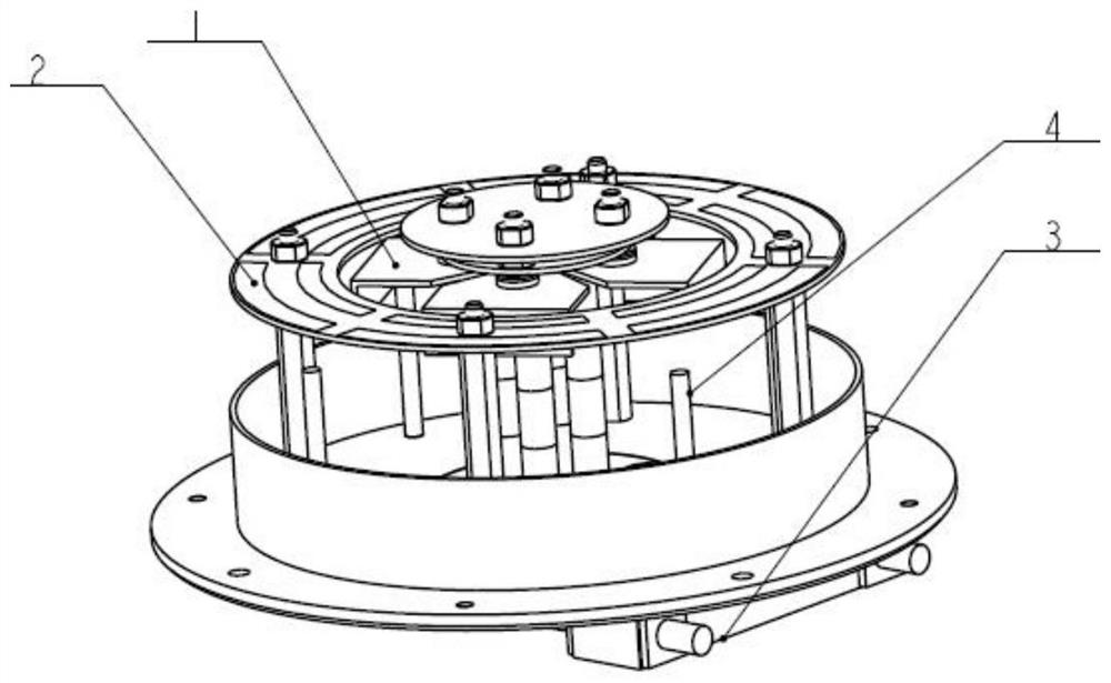
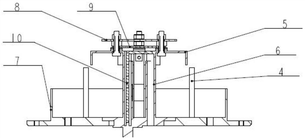
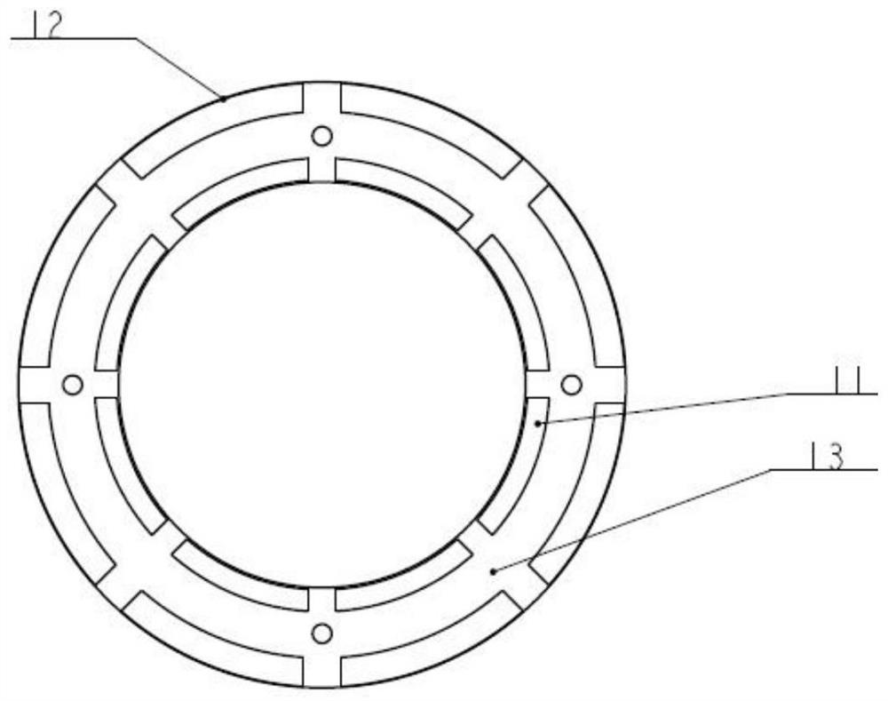
[0022] A wide-band stable wide-beam cavity dipole antenna device, which includes a wide-band cross cavity dipole antenna, double choke rings, metal isolation posts, and a broadband circularly polarized bridge. The end of the radiation vibrator piece has a downward It is bent at 90 degrees, and a pair of metal matching discs are connected by dielectric screws at the top; the geom...


PUM


Abstract

The invention discloses a broadband stable wide-beam cavity oscillator antenna, and belongs to the technical field of antennas. The antenna comprises a broadband crisscross cavity oscillator antenna, double choke rings, a broadband circularly polarized bridge and a metal reflection back cavity; the cavity oscillator antenna is fixed right above the metal reflection back cavity through a metal support column, and the broadband circularly polarized bridge is arranged at the outer bottom of the metal reflection back cavity; the cavity oscillator antenna comprises a cross-shaped radiation oscillator sheet and a metal matching disc group; the metal matching disc group is fixed above the cross-shaped radiation oscillator sheet through a medium screw; the double choke rings are fixed above the metal reflection back cavity through the medium support columns; the radiation oscillator sheet is located in the double-choke ring and is located at the same height as the double-choke ring; the plurality of metal isolation columns are uniformly arranged at the bottom in the metal reflection back cavity, and the height of the tops of the metal isolation columns is lower than the height of the radiation oscillator sheets. According to the invention, the wide beam width of the traditional broadband antenna is expanded.

Description

technical field [0001] The invention relates to the technical field of antennas, in particular to a broadband stable wide beam cavity dipole antenna. Background technique [0002] In radio communication systems such as satellite positioning, radar detection, electronic countermeasures, and missile-borne measurement and control, in order to ensure signal transmission quality and transmission rate, the antenna often needs to have a wide beamwidth and a wide frequency band. In wide-beam applications, it is generally required that the half-power lobe width of the pattern be within the range of 90 degrees to 110 degrees within the frequency band. The structural forms of wide beam antennas in engineering include helical antennas, microstrip antennas, cross dipole antennas, slot antennas, etc., but there are more or less shortcomings such as narrow working bandwidth and narrow beam width. In addition, because the matching bandwidth of the antenna does not coincide with the axial r...

Claims


Application Information

Patent Timeline
Patent Type & Authority Applications(China)
IPC IPC(8): H01Q5/50H01Q5/20H01Q3/00H01Q15/14H01Q19/10H01Q1/36
CPCH01Q5/50H01Q5/20H01Q3/00H01Q15/14H01Q19/10H01Q1/36
Inventor 张晓冲李少恩何其洪马剑南蒋博赵东贺卢飞宇李增科刘桂凤吴伟伟汪龙溪
Owner NO 54 INST OF CHINA ELECTRONICS SCI & TECH GRP
Why Eureka
Try Eureka