
Energy feedback device in converter load test

A technology of energy feedback and load test, applied in the field of converters, to reduce costs, simplify the overall circuit, and reduce power consumption

Pending Publication Date: 2022-02-22
GUIZHOU UNIV OF ENG SCI
View PDF0 Cites 0 Cited by
  • Summary
  • Abstract
  • Description
  • Claims
  • Application Information

AI Technical Summary

Problems solved by technology

[0003] The technical problem to be solved by the present invention is to overcome the defects of the prior art, and provide an energy feedback device in the load test of the converter, which can effectively reduce the power consumption in the load test process, and the overall circuit is relatively simple, easy to operate, and extremely Great need to reduce costs

Method used


Image

  • Energy feedback device in converter load test
  • Energy feedback device in converter load test
  • Energy feedback device in converter load test

Examples


Embodiment 1

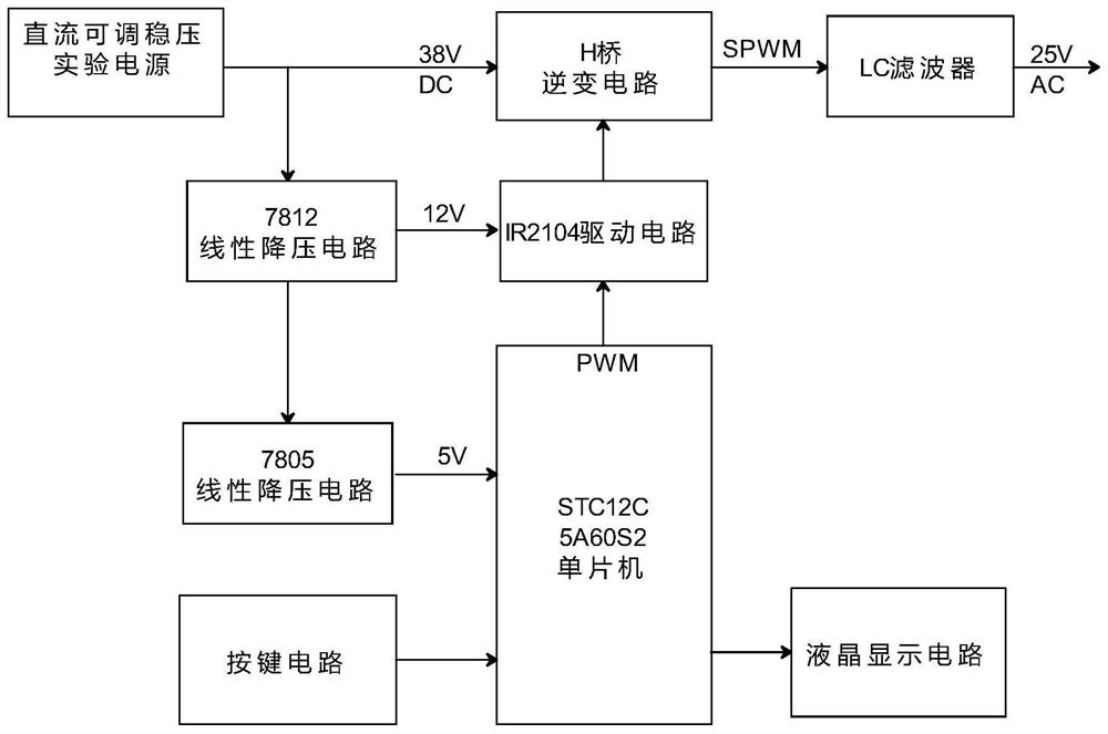
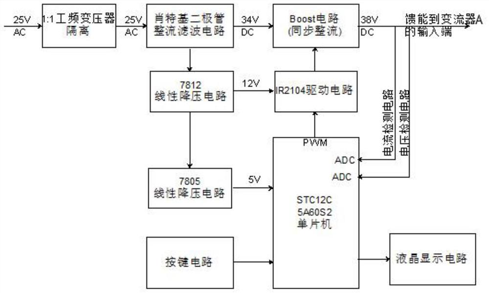
[0022] Such as figure 1 As shown, the present invention provides an energy feedback device in a converter load test, including an energy feedback device, a converter A and a DC power supply, the energy feedback device includes a connection unit and a converter B, and the converter carries out During the load test, a load must be connected to its output terminal. Normally, the output power is consumed at this load. In order to save energy, energy feedback should be carried out. During the load test, the converter A converts the DC power of the DC power supply into AC power, and its output is connected to the converter B through the connection unit. The converter B converts the AC power into a DC power and feeds it back to the input terminal of the converter A. Together with the DC power supply, power is supplied to the converter A, thereby realizing energy saving.

[0023] Specifically, the inverter part of the present invention adopts an open-loop design. After isolation wi...

Embodiment approach

[0036]Option 1: Hall current sensor. Current flows through the coil of the Hall sensor to generate a magnetic field. The magnetic field changes with the magnitude of the current. The magnetic field gathers in the magnetic ring, and the output voltage signal of the Hall element changes with the magnetic field. After detecting the voltage value, the magnitude of the current can be obtained.

[0037] Option 2: Resistor voltage divider detection circuit. By connecting the sampling resistor in series in the output circuit, the current passing through the resistor is converted into a voltage at both ends, and the current value is obtained by detecting the voltage value. The detection mode circuit and program control are relatively simple.

[0038] Converter A and converter B both include a system power supply circuit, a key circuit and a display circuit, the input end of the system power supply circuit of converter A is connected to the DC power supply, and the input end of the sy...


PUM


Abstract

The invention discloses an energy feedback device in a converter load test, which comprises an energy feedback device, a converter A and a direct-current power supply. The energy feedback device comprises a connecting unit and a converter B. The connecting unit adopts an isolation transformer. The converter A adopts a single chip microcomputer A to output SPWM waveforms to an H-bridge inverter circuit. The H-bridge inverter circuit converts direct current input by the direct-current power supply into alternating current and outputs the alternating current to the energy feedback device. The converter B outputs SPWM waveforms to a BOOST circuit through a single-chip microcomputer B, and the BOOST circuit converts the input alternating current into direct current and feeds the direct current back to the input end of the converter A. According to the energy feedback device, part of electric energy is fed back to the input end of the converter, electric energy consumption in the load experiment process can be effectively reduced, the whole circuit is simple, the operation is easy and convenient, and the cost requirement is greatly reduced.

Description

technical field [0001] The invention relates to the technical field of converters, in particular to an energy feedback device in a converter load test. Background technique [0002] In the process of research and development and production, a large number of load devices are needed for experiments. However, at present, large-capacity load devices need to consume a large amount of electric energy during the experiment process, which leads to an increase in the cost of the experiment process. Energy issues are increasingly Seriously today, the high consumption of the load is increasingly unsuitable for development, so it is necessary to design an energy feedback device to deal with the above problems. Contents of the invention [0003] The technical problem to be solved by the present invention is to overcome the defects of the prior art, and provide an energy feedback device in the load test of the converter, which can effectively reduce the power consumption in the load te...

Claims


Application Information

Patent Timeline
IPC IPC(8): H02J1/10H02M3/335
CPCH02J1/10H02J1/102H02M3/33576H02M3/33592
Inventor 李佐刘倩廖大麟王建卫何启鹏孔维焱杨文勇梁红应
Owner GUIZHOU UNIV OF ENG SCI
Learn More