Variable-rigidity vibration isolation device for punching machine

A technology of rigidity and punching, which is applied in the field of machine tool equipment, can solve the problems of reduced machining accuracy, lack of shock absorption effect, and influence on machine tool stability, etc., and achieve good vibration reduction effect, small vibration amplitude, and high machining accuracy. Effect

Active Publication Date: 2022-02-25
汕头职业技术学院
View PDF15 Cites 0 Cited by
  • Summary
  • Abstract
  • Description
  • Claims
  • Application Information

AI Technical Summary

Problems solved by technology

However, the spring in the above-mentioned machine tool damping device is a coil spring, and the stiffness of the coil spring will not change. When a coil spring with a smaller stiffness is used, the vibration amplitude of the machine tool becomes larger during the damping process, resulting in The accuracy is reduced; when using a coil spring with a higher stiffness, the shock absorption effect cannot be achieved, which affects the stability of the machine tool

Method used


Image

  • Variable-rigidity vibration isolation device for punching machine
  • Variable-rigidity vibration isolation device for punching machine
  • Variable-rigidity vibration isolation device for punching machine

Examples


Embodiment 1

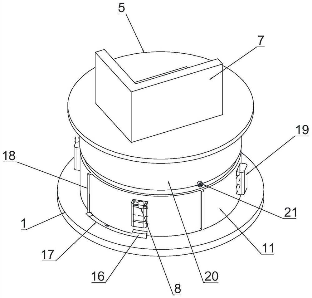
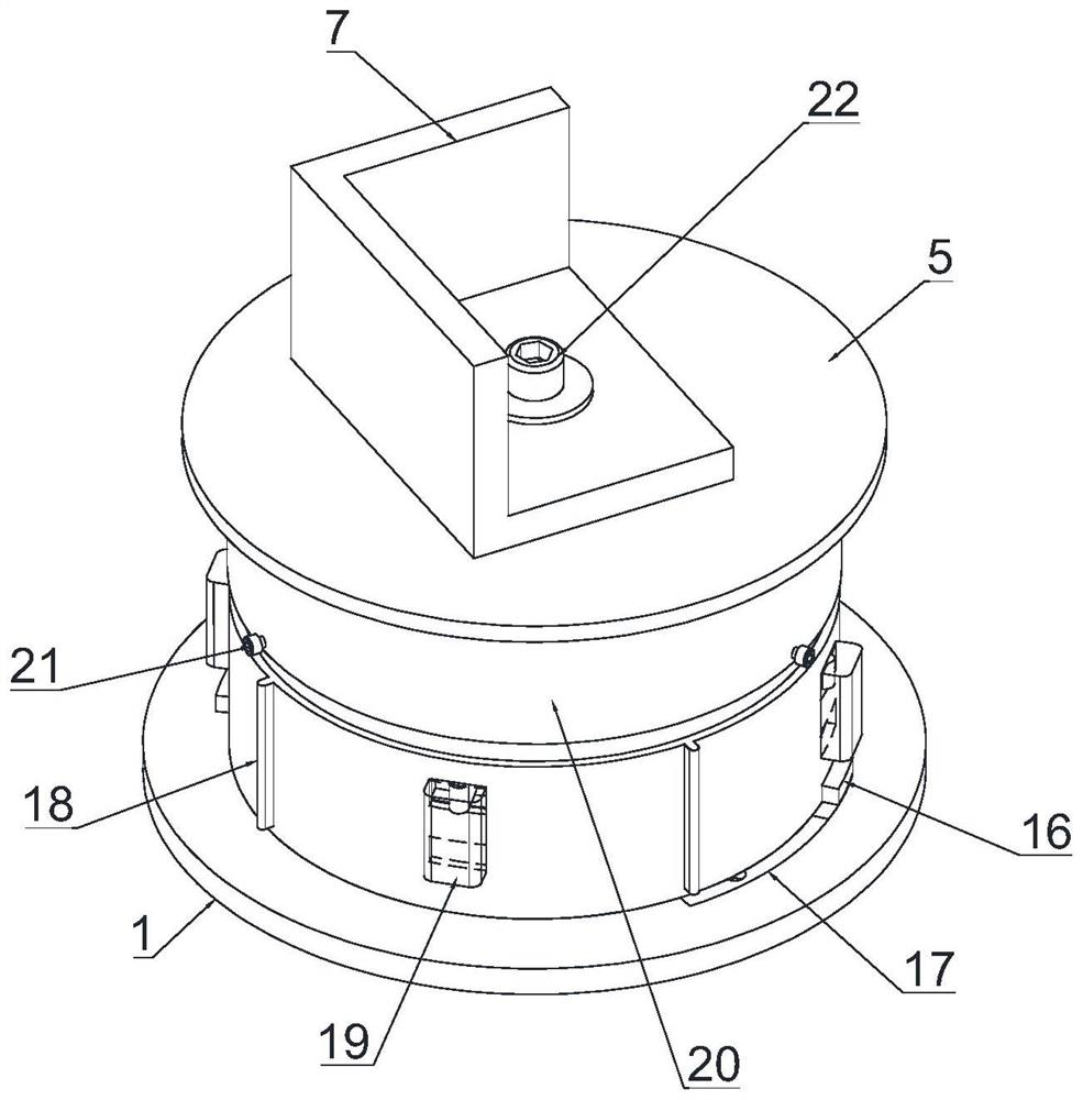
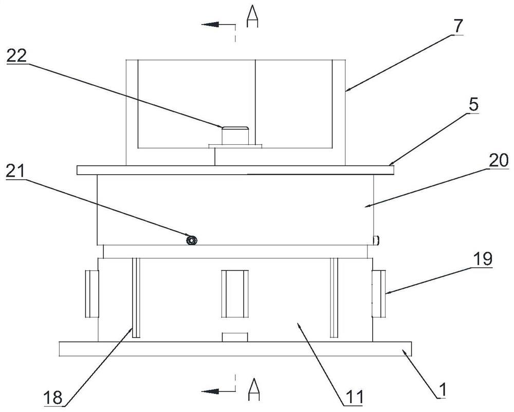
[0036] see Figure 1-Figure 4 , this embodiment discloses a punch press vibration isolation device with variable stiffness, including a base 1, a cylinder 2, a guide cylinder 3, a pressure plate 4, a support plate 5, eight disc reeds 6 and a disc reed for adjusting 6 working quantity adjustment mechanism; the lower end of the cylinder 2 and the guide cylinder 3 are fixedly connected to the base 1, the guide cylinder 3 is located inside the cylinder 2 and coaxially arranged with the cylinder 2; The pressure plate 4 is arranged between the support plate 5 and the guide cylinder 3, the upper end of the pressure plate 4 is connected with the support plate 5, and the lower end is slidingly connected with the outer wall of the guide cylinder 3; the machine foot 7 of the machine tool is set On the support plate 5, the machine foot 7, the support plate 5 and the pressure plate 4 are fixedly connected by bolts 22 between the machine foot 7 and the pressure plate 4; eight disc springs 6...

Embodiment 2

[0055] Other structures in this embodiment are the same as in Embodiment 1, the difference is that the sliding sleeve 20 and the pressure plate 4 are integrally structured, and the advantage is that the sliding sleeve 20 and the pressure plate 4 can slide up and down stability, thereby improving the stability of the machine foot 7.

Embodiment 3

[0057] Other structures in this embodiment are the same as in Embodiment 1, except that the number of disc springs 6 can be other numbers, such as nine, and each area is divided into three evenly. The thickness of each disc spring 6 can be different from each other, and the thickness of the disc springs 6 in each region can also be different from each other; the advantage can make the disc spring 6 have better rigidity.


PUM


Abstract

The invention discloses a variable-rigidity vibration isolation device for a punching machine, which comprises a base, a cylinder, a guide cylinder, a pressing disc, a supporting plate and a plurality of disc reeds, wherein the upper end of the pressing disc is connected with the supporting plate, and the lower end of the pressing disc is slidably connected with the outer wall of the guide cylinder; and the plurality of disc reeds are positioned between the guide cylinder and the cylinder, and are sequentially connected end to end in a zigzag shape from top to bottom. The device further comprises an adjusting mechanism, wherein the adjusting mechanism comprises at least one top plate, a clamping block mechanism and an adjusting driving mechanism; and the top plate divides the space between the cylinder and the guide cylinder into a plurality of areas up and down, and the plurality of disc reeds are respectively distributed in the areas. The rigidity of the vibration isolation device can be changed, the change of the rigidity can be flexibly adjusted, so that a load-deformation curve is nonlinear, the vibration energy absorption efficiency is high, and the vibration reduction effect is good. In addition, the vibration amplitude of a machine tool is not large in the vibration reduction process, the machining precision of the machine tool is higher, and the stability of the machine tool is higher.

Description

technical field [0001] The invention relates to the technical field of machine tool equipment, in particular to a punching vibration isolation device with variable stiffness. Background technique [0002] As a machine for manufacturing machines, machine tools are widely used in actual production. When the machine tool is working, it usually produces a large vibration, which affects the stability of the bed body and generates a lot of noise. The machine tool shock absorber is a machine tool support device used to reduce the vibration of the bed body. It is easy to install. Greatly enhanced the overall performance of the machine tool. [0003] For example, the authorized announcement number is CN204647113U utility model patent discloses a kind of machine tool damping device, comprises thick upright nut, spring cover, iron net, iron seat, spring; Described thick upright nut runs through the whole iron net; Described spring The cover is set on the upper end of the thick vertic...

Claims


Application Information

Patent Timeline
Patent Type & Authority Applications(China)
IPC IPC(8): F16F15/073F16M7/00
CPCF16F15/073F16M7/00
Inventor 魏协奔
Owner 汕头职业技术学院
Why Eureka
Try Eureka