
Industrial kiln

An industry and kiln technology, applied in the direction of furnace, furnace components, burning with multiple fuels, etc., can solve the problems of heat redundancy, uniform temperature, extreme temperature difference in space, etc., and achieve the effect of increasing heat and increasing flow rate

Inactive Publication Date: 2022-02-25
陈迪丰
View PDF0 Cites 0 Cited by
  • Summary
  • Abstract
  • Description
  • Claims
  • Application Information

AI Technical Summary

Problems solved by technology

In addition, the separation of vanadium-titanium magnetite and vanadium-titanium separation also requires a stable temperature field. The existing industrial furnaces cannot guarantee that the temperature in each part of the furnace is uniform, and it is difficult to maintain a uniform and stable furnace temperature.
[0003] Since there is a sealed heating space in the industrial kiln, the traditional heating method concentrates the heat on the annular inner wall of the industrial kiln, so that the heat will radiate from the annular inner wall to the center of the industrial kiln, and the center position is generally Place the processed parts, which will cause the internal parts of the fired products to be heated insufficiently, which will cause quality problems in the production of the products, and during the firing process, the heat in the indoor part is redundant, and the temperature in some spaces is extremely high. Poor problem, so the same product has multiple firing temperatures, the heat is not fully utilized, and the efficiency of heating and heating is low

Method used


Image

  • Industrial kiln
  • Industrial kiln
  • Industrial kiln

Examples


Embodiment Construction

[0027] The following will clearly and completely describe the technical solutions in the embodiments of the present invention with reference to the accompanying drawings in the embodiments of the present invention. Obviously, the described embodiments are only some, not all, embodiments of the present invention. Based on the embodiments of the present invention, all other embodiments obtained by persons of ordinary skill in the art without making creative efforts belong to the protection scope of the present invention.

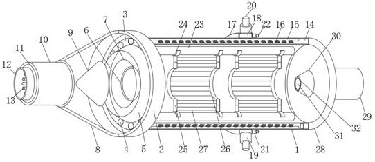
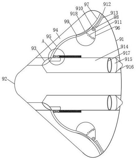
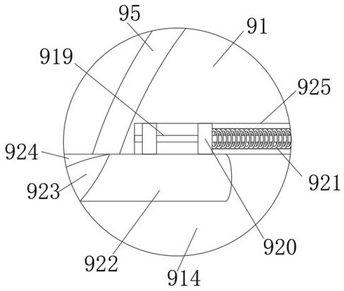
[0028] Such as Figure 1-5 As shown, the present invention provides a technical solution: an industrial kiln, including an industrial kiln chamber 1, an annular mounting plate 2 is fixedly connected to the left side of the industrial kiln chamber 1, and the inner cavity of the industrial kiln chamber 1 is connected to the annular mounting plate 2 The inner cavity of the ring-shaped mounting plate 2 is provided with a built-in mounting ring 3, and a plurality o...


PUM


Abstract

The invention relates to the technical field of industrial kilns, and discloses an industrial kiln which comprises an industrial kiln chamber. An annular mounting plate is fixedly connected to the left side of the industrial kiln chamber, an inner cavity of the industrial kiln chamber communicates with an inner cavity of the annular mounting plate, and a built-in mounting ring is arranged in the annular mounting plate in a sleeved mode. A plurality of mounting grooves are formed in the built-in mounting ring, built-in heat pipes are arranged in the mounting grooves, and a pressure port pipe is arranged at the axis of the inner wall of the annular mounting plate. Air flow generated by the air increasing pump can increase the heat dispersion efficiency, the uniform heating efficiency in the industrial kiln chamber is improved, heat can flow back into the conical heat release cover from the interior of the industrial kiln chamber through the pressure port pipe, in this way, circulation of the air flow is formed, the heat can be fully circulated, and then the firing quality of the industrial kiln is improved; and the condition of heat waste caused by heat accumulation is avoided.

Description

technical field [0001] The invention relates to the technical field of industrial furnaces, in particular to an industrial furnace. Background technique [0002] In the general industrial heat treatment process, it is necessary to determine the parameters such as the heating curve and solid solution time of the alloy parts, so that the alloy parts can obtain a uniform mechanical property. Especially for fired products during heat treatment, the molding of fired products requires a very smooth growth curve. This smooth production curve is difficult to control in an uneven temperature field, and whether the quality of fired products is consistent with this temperature field Uniform has a large correlation. In addition, vanadium-titanium magnetite separation and vanadium-titanium separation also require a stable temperature field. Existing industrial furnaces cannot guarantee that the temperature in each part of the furnace is uniform, and it is difficult to maintain a uniform...

Claims


Application Information

Patent Timeline
Patent Type & Authority Applications(China)
IPC IPC(8): F27D3/12F27D7/02F28D15/02F23C5/08
CPCF27D3/123F27D7/02F28D15/02F23C5/08
Inventor 陈迪丰
Owner 陈迪丰
Learn More