
Isolated temperature sensing for electrical terminals

A technology of electrical terminals and electrical isolation, applied in the direction of thermometers, thermometers, and thermometers with physical/chemical changes that are directly sensitive to heat, electric/magnetic components, etc., can solve the problem of pin cross-sectional area reduction and ohmic heating increase , resistance increase and other issues

Pending Publication Date: 2022-02-25
ティーイーコネクティビティサービシーズゲーエムベーハー
View PDF0 Cites 0 Cited by
  • Summary
  • Abstract
  • Description
  • Claims
  • Application Information

AI Technical Summary

Problems solved by technology

However, a disadvantage of any such embedded sensor is the reduced pin cross-sectional area required to accommodate the sensor volume, which results in increased resistance and increased ohmic heating
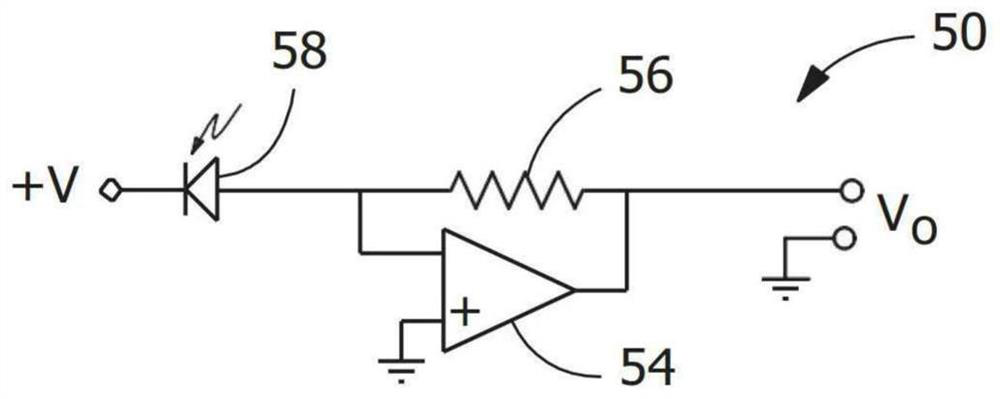
[0005] The problem to be solved is to provide a remote sensing circuit and method in which the components provide galvanic isolation without increasing the measurement system time constant and without reducing the pin cross-sectional area caused by the existing solutions described above

Method used


Image

  • Isolated temperature sensing for electrical terminals
  • Isolated temperature sensing for electrical terminals
  • Isolated temperature sensing for electrical terminals

Examples


Embodiment Construction

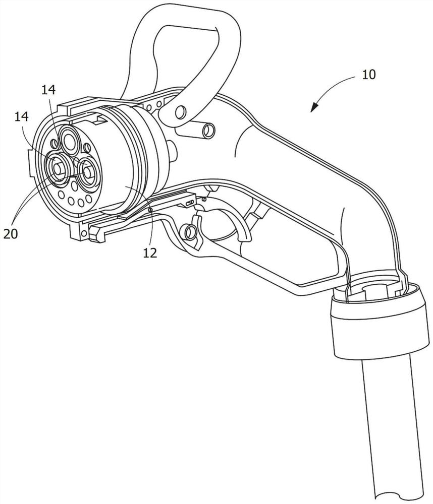
[0016] refer to figure 1 , shows a representative charging port connector 10 incorporating electrical terminals 20 and an isolated temperature sensing system, as will be described more fully, for sensing the temperature of electrical terminals 20 . The connector 10 has a housing 12 in which a terminal accommodating chamber 14 is disposed. The terminal accommodating cavity 14 is configured to accommodate the terminal 20 therein. The specific configuration and shape of the connectors may vary without departing from the scope of the present invention.

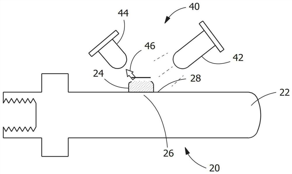
[0017] exist figure 2 In the illustrative embodiment shown, terminal 20 is in the shape of a pin having a free end 22 configured to mate with a mating connector (not shown) provided in a vehicle or the like. The size and shape of the terminal 20 can vary depending on the application and the amount of current that the terminal 20 must carry.

[0018] A sheet of material 24 is applied to a region 26 of each terminal 20 . The s...


PUM

PropertyMeasurementUnit
lengthaaaaaaaaaa
widthaaaaaaaaaa
thicknessaaaaaaaaaa

Abstract

A method of detecting temperature of an electrical terminal (20, 120) is disclosed. The method includes: applying a material patch (24, 124) to a surface of the electrical terminal (20, 120), the thermal mass of the material patch (24, 124) is less than 25 percent of the thermal mass of the electrical terminal (20, 120), whereby the material patch (24, 124) does not appreciably increase the electrical resistance or thermal capacitance of the electrical terminal (20, 120); and remotely sensing a change in the material patch (24, 124) with an electrically isolated circuit (50, 150) which is external to the electrical terminal (20, 120) to determine if the electrical terminal (20, 120) is operating at a safe temperature to optimize current flow across the electrical terminal (20, 120).

Description

technical field [0001] The present invention relates to an apparatus and method for remote and isolated temperature sensing of electrical terminals. Background technique [0002] The current rating of electric vehicle (EV) charging port connectors is currently limited by contact temperature. The contact temperature method of connector derating allows the charging system to maximize charging current (and minimize charging time) while avoiding damage to the charging port connector. Key attributes of a suitable temperature sensor include high accuracy, fast response time, and low cost. [0003] The accuracy and response time of traditional sensors such as resistive temperature sensors (RTDs) or thermocouples can be limited because they need to be electrically isolated from the contact pins. The additional material required for electrical isolation increases the thermal resistance and thermal capacitance of the sensing system. Additional resistance reduces absolute measuremen...

Claims


Application Information

Patent Timeline
Patent Type & Authority Applications(China)
IPC IPC(8): G01K11/12G01K5/52G01K7/36H02J7/00B60L53/16H01R13/66C09D11/50G09F3/00
CPCH01R13/6683B60L53/16C09D11/50G09F3/0294G01K5/52G01K7/36G01K11/12B60L53/302B60L53/62Y02T10/70Y02T10/7072Y02T90/12Y02T90/14G01K7/023G01K7/16
Inventor D.B.萨拉夫M.K.迈尔斯M.瓦滕伯格
Owner ティーイーコネクティビティサービシーズゲーエムベーハー
Learn More