
A cross-linking agent production device based on high-pressure filtration for oil fields
A production device and cross-linking agent technology, applied in filtration and separation, fixed filter elements, transportation and packaging, etc., can solve the problems of impurities in raw materials, poor mixing effect of cross-linking agents in oil fields, and low filtration efficiency of cross-linking agents, etc. problem, to achieve the effect of increasing filtration and purification efficiency
- Summary
- Abstract
- Description
- Claims
- Application Information
AI Technical Summary
Problems solved by technology
Method used
Image

Examples
Embodiment 1
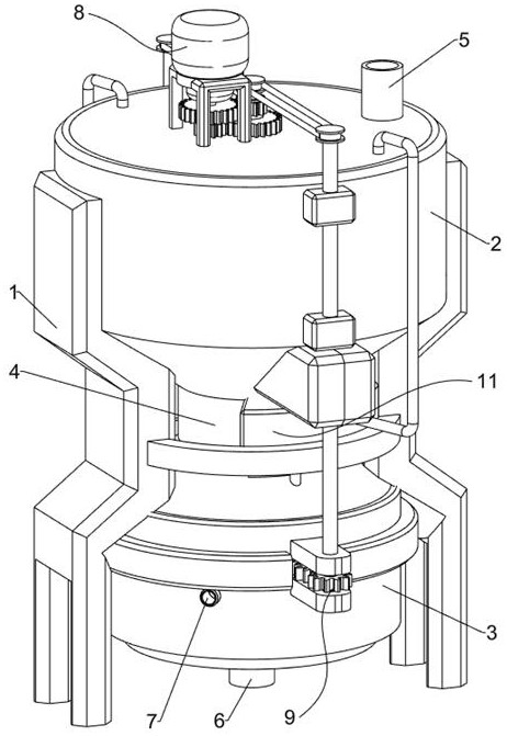
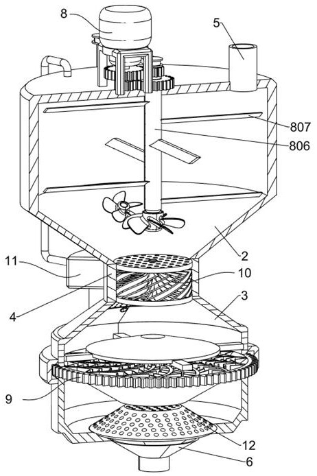
[0029] A cross-linking agent production device based on high-pressure filtration for oil fields, such as figure 1 and figure 2 As shown, it includes a fixed frame 1, an upper chamber body 2, a lower chamber body 3, a filter cartridge 4, a feed port 5, a discharge port 6, a high-pressure ventilation port 7, a circulating stirring part 8, a mixing stirring part 9, a filter The component 10 and the purification net 12, the upper part of the fixing frame 1 is fixedly connected with the upper cavity 2, the lower part of the upper cavity 2 is set in the shape of an inverted truncated cone, the lower part of the fixing frame 1 is fixedly connected with the lower cavity 3, and the upper part of the lower cavity 3 is in the shape of a truncated cone The middle part of the lower chamber 3 protrudes outwards, the filter cartridge 4 is arranged between the upper chamber 2 and the lower chamber 3, the filter cartridge 4 is symmetrically provided with a feed grid and a chute, and the upper...
Embodiment 2
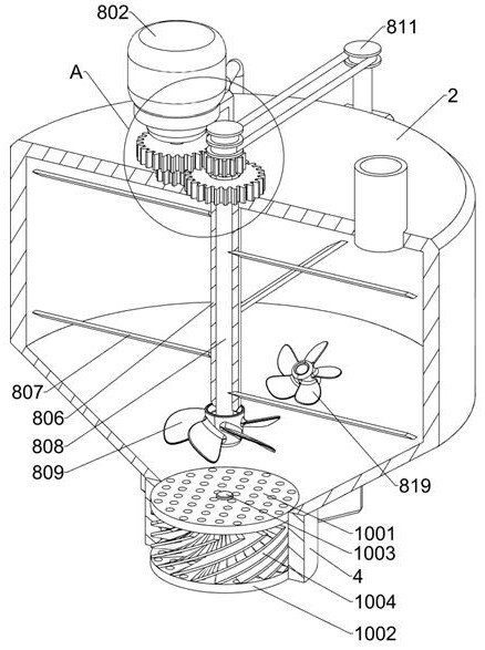
[0032] On the basis of Example 1, such as Figure 3-Figure 5 As shown, the circulating stirring part 8 includes a motor frame 801, a servo motor 802, a first spur gear 803, a second spur gear 804, a third spur gear 805, a sleeve rod 806, a diamond-shaped stirring rod 807 and a circulation assembly, and the motor frame 801 Fixed on the upper surface of the upper cavity 2, the servo motor 802 is arranged on the motor frame 801, the lower end of the output shaft of the servo motor 802 is provided with a rotating shaft, and the first spur gear 803 and the second spur gear are fixed on the rotating shaft of the servo motor 802 804, the sleeve rod 806 is slidably arranged on the upper surface of the upper cavity 2, the upper end of the sleeve rod 806 is fixedly connected with the third spur gear 805, the third spur gear 805 meshes with the second spur gear 804, and the sleeve rod 806 is provided with several Two diamond-shaped stirring rods 807, two diamond-shaped stirring rods 807 ...
Embodiment 3
[0041] On the basis of Example 2, such as figure 2 , Figure 9 and 10 As shown, it also includes an impurity collecting part 11, and two groups of impurity collecting parts 11 are symmetrically arranged front and back, and the impurity collecting part 11 includes a second protective shell 1101, a sliding sleeve 1102, an air pipe 1103, an arc-shaped sliding rod 1104, and a piston plate 1105, push plate 1106, connection block 1107, grid baffle plate 1108, impurity collection shell 1109 and the third filter plate 1110, the second protective shell 1101 is fixedly connected on the peripheral wall of the filter cartridge 4, and the sliding sleeve 1102 is arranged on the second Inside the protective case 1101, the outer end and the lower end of the sliding sleeve 1102 are respectively connected with a ventilation tube 1103, and the ventilation tube 1103 is used to connect the sliding sleeve 1102 with the upper cavity 2 and the lower cavity 3 respectively, and the arc-shaped sliding...
PUM
 Abstract
Description
Claims
Application Information