Denitration combustion device of biomass boiler

A biomass boiler and combustion device technology, applied in the direction of combustion method, combustion type, combustion equipment, etc., can solve problems such as corrosion of the inner wall of the pipeline, and achieve the effects of avoiding corrosion, increasing service life, and improving cleaning effect

Pending Publication Date: 2022-03-01
邓小姣
View PDF1 Cites 0 Cited by
  • Summary
  • Abstract
  • Description
  • Claims
  • Application Information

AI Technical Summary

Problems solved by technology

[0006] In order to make up for the deficiencies of the existing technology and solve the high content of sulfur trioxide in the flue gas produced by burning straw in the prior art, when the flue gas passes through the pipe of the burner, sulfur trioxide will form sulfate on the inner wall of the pipe, due to sulfuric acid Salt has a certain corrosiveness and will corrode the inner wall of the pipeline. The present invention proposes a biomass boiler denitrification combustion device

Method used


Image

  • Denitration combustion device of biomass boiler
  • Denitration combustion device of biomass boiler
  • Denitration combustion device of biomass boiler

Examples


Embodiment 1

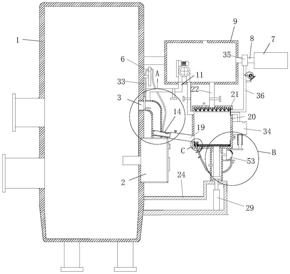
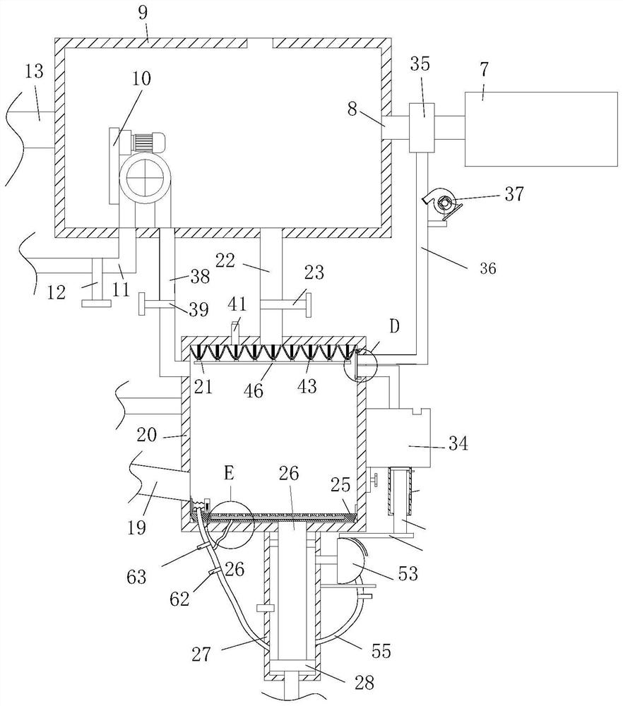
[0034] Such as Figure 1 to Figure 4 As shown, the biomass boiler denitrification combustion device described in the embodiment of the present invention includes a furnace body 1; A pipeline 3 is communicated between them. A water tank 9 is provided on one side of the furnace body 1. The water tank 9 is fixedly connected with the furnace body 1 by means of a bracket. A water inlet is provided at the top of the water tank 9. There is a heating pipe 8, the other end of the heating pipe 8 is fixedly installed with a natural gas heater 4, the bottom end of the water tank 9 is communicated with a water inlet pipe 11, and a first valve 12 is installed on the water inlet pipe 11, and the inlet The end of the water pipe 11 far away from the water tank 9 communicates with the pipeline 3, and the water retaining plate 15 is slidably connected to the pipe 3, and the surface of the water retaining plate 15 is sealed and connected to the pipe 3, and the water outlet pipe 14 is slidably con...

Embodiment 2

[0043] Such as Figure 3 to Figure 10 Shown, comparative example one, wherein another kind of implementation mode of the present invention is:

[0044] A third air valve 63 is installed on the second air pipe 56, an elastic rope 69 is fixedly installed between the sliding block 60 and the support plate 58, a rectangular groove is opened inside the bottom plate 25, and a pusher is sealed in the rectangular groove. plate 66, the top of the pushing plate 66 is evenly fixed with a sliding post 65, the sliding post 65 is connected to the inside of the bottom plate 25 by sliding, the bottom end of the scraper 61 is arc-shaped, and one of the scraper 61 The connection drive plate 68 on the side, the second spring 67 is fixedly connected between the drive plate 68 and the sliding block 60, the bronchus 64 is communicated with the second air pipe 56, and the bronchus 64 communicates with the rectangular groove, by opening the third Air valve 63, and close the air valve, use the air in...


PUM


Abstract

The invention belongs to the field of boiler combustion equipment, and particularly relates to a biomass boiler denitration combustion device which comprises a boiler body. A low-nitrogen combustor is fixedly connected to the side wall of the furnace body, a pipeline is communicated between the low-nitrogen combustor and the furnace body, a water tank is arranged on one side of the furnace body, the water tank is fixedly connected with the furnace body through a support, a water inlet is formed in the top end of the water tank, and a heating pipe is communicated in the water tank. A natural gas heater is fixedly installed at the other end of the heating pipe, the bottom end of the water tank communicates with a water inlet pipe, a first valve is installed on the water inlet pipe, the end, away from the water tank, of the water inlet pipe communicates with a pipeline, and a water baffle is slidably connected into the pipeline. Warm water in the water tank enters the pipeline from the water inlet pipe, sulfate on the inner wall of the pipeline can be washed by the warm water, the effect of washing the sulfate on the inner wall of the pipeline is achieved, the situation that the sulfate corrodes the inner wall of the pipeline is avoided, and the service life of the pipeline is prolonged.

Description

technical field [0001] The invention relates to the field of boiler combustion equipment, in particular to a biomass boiler denitrification combustion device. Background technique [0002] Biomass refers to straw and wood chips. The boiler uses a low-nitrogen burner to burn the straw, and then denitrifies the flue gas generated during the combustion. [0003] There are also some technical solutions about boiler combustion equipment in the prior art. For example, a Chinese patent with application number CN201510073991.0 discloses a biomass boiler denitrification combustion device and a double-burner biomass boiler, including a combustion chamber and a device. The burner in the combustion chamber has a feed inlet and an air inlet in the middle of one end of the combustion chamber, and a flame nozzle at the other end of the combustion chamber. In particular, the outer layer of the flame nozzle is provided with a coaxial outer casing of the nozzle. The tube-in-tube tube and the...

Claims


Application Information

Patent Timeline
Patent Type & Authority Applications(China)
IPC IPC(8): F23C5/08F23J3/02F28G9/00
CPCF23C5/08F23J3/02F28G9/00
Inventor 邓小姣
Owner 邓小姣
Why Eureka
Try Eureka