
Photoetching machine system and photoetching method

A lithography machine and lithography technology, applied in the field of lithography machines, can solve problems such as limitations, achieve the effects of reducing power consumption, reducing line width infinitely, and improving lithography precision

Pending Publication Date: 2022-03-01
深圳市笨辉光电科技有限公司
View PDF0 Cites 0 Cited by
  • Summary
  • Abstract
  • Description
  • Claims
  • Application Information

AI Technical Summary

Problems solved by technology

[0003] The invention provides a lithography machine system and a lithography method, which are used to solve the problem in the prior art that the lithography beam will be limited after being adjusted to a certain threshold

Method used


Image

  • Photoetching machine system and photoetching method
  • Photoetching machine system and photoetching method
  • Photoetching machine system and photoetching method

Examples


Embodiment Construction

[0033] Embodiments of the present invention are described in detail below, examples of which are shown in the drawings, wherein the same or similar reference numerals designate the same or similar elements or elements having the same or similar functions throughout. The embodiments described below by referring to the figures are exemplary only for explaining the present invention and should not be construed as limiting the present invention.

[0034] In describing the present invention, it should be understood that the terms "center", "longitudinal", "transverse", "length", "width", "thickness", "upper", "lower", "front", " Back", "Left", "Right", "Vertical", "Horizontal", "Top", "Bottom", "Inner", "Outer", "Clockwise", "Counterclockwise", "Axial" , "radial", "circumferential" and other indicated orientations or positional relationships are based on the orientations or positional relationships shown in the drawings, which are only for the convenience of describing the present ...


PUM


Abstract

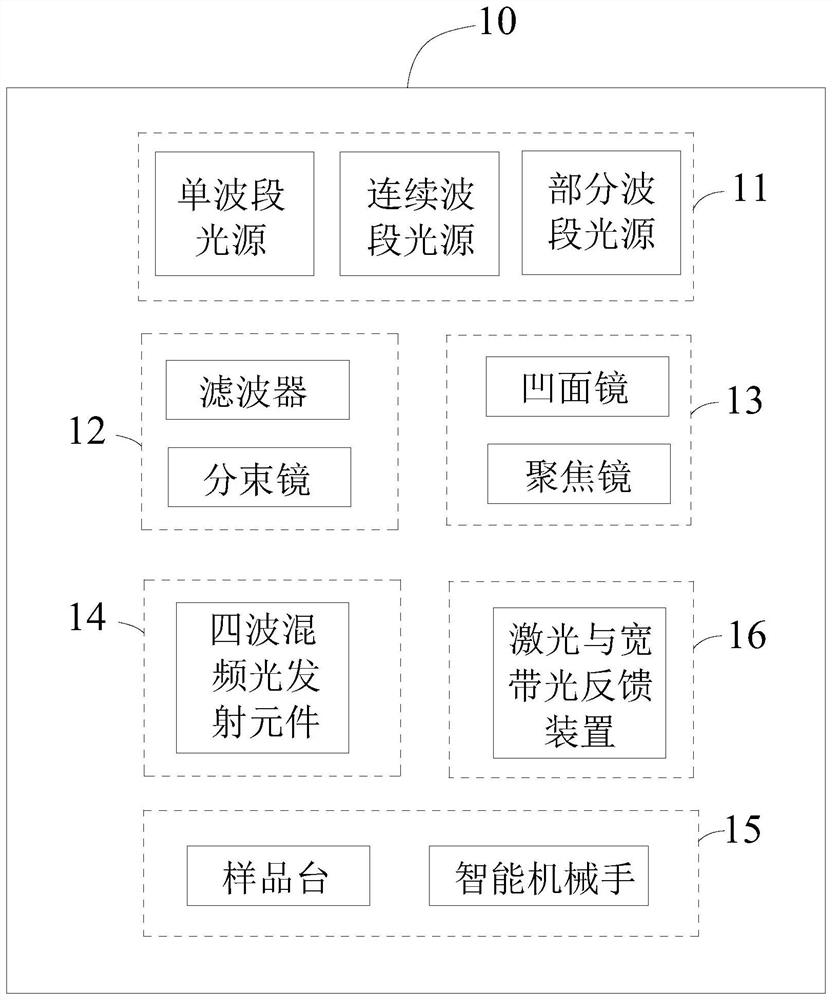
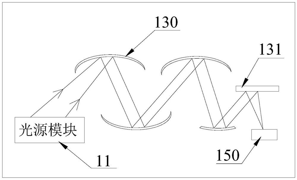
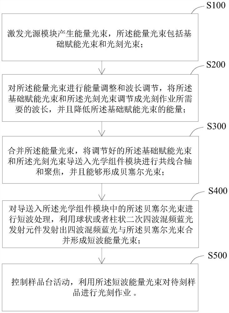
The invention relates to the technical field of photoetching machines, in particular to a photoetching machine system and a photoetching method. The photoetching machine system comprises a light source module, wherein the light source module can emit at least two energy light beams; the energy beam adjusting module is used for adjusting the wavelength and energy of the energy beam; the optical assembly module is used for carrying out collinear axis combination and focusing on the energy light beams to form Bessel light beams; the four-wave mixing light emitting module is used for providing four-wave mixing blue light, and the four-wave mixing blue light and the Bessel beam are subjected to collinear axis combination and focusing to form a short-wave energy beam; the movement assembly module comprises a sample table and an intelligent manipulator, the sample table is set to be in a position moving state, the intelligent manipulator is used for adjusting the position of a sample to be etched on the sample table, the line width of a photoetching light beam can be reduced infinitely through the system, the light beam can be reduced to 5nm, 3nm, 2nm or even lower, and the accuracy of photoetching is improved. And the power consumption is reduced while the photoetching precision is improved.

Description

technical field [0001] The invention relates to the technical field of lithography machines, in particular to a lithography machine system and a lithography method. Background technique [0002] The existing cutting-edge lithography technology on the market is extreme ultraviolet lithography, which usually uses a 13.5nm extreme ultraviolet light source for short-pulse lithography, and the combination of extreme ultraviolet lithography and etching technology can make the chip process achieve 5nm, and even combined with etching technology to further upgrade the 5nm process to 3nm. This currently used technology is based on the Abbe imaging diffraction limit, that is, the technology realized by using Rayleigh optical modulation technology after the interaction between light and matter. This traditional technology has its own Limitations, the requirements for light source and working wavelength beam energy are quite high. Contents of the invention [0003] The invention prov...

Claims


Application Information

Patent Timeline
Patent Type & Authority Applications(China)
IPC IPC(8): G03F7/20
CPCG03F7/70058G03F7/70725
Inventor 侯国辉侯国利刘友兰侯利艳
Owner 深圳市笨辉光电科技有限公司
Learn More