
Porous ceramic structure

A ceramic structure, porous technology, applied in ceramic products, gas treatment, catalyst carrier and other directions, can solve problems such as pressure loss increase, and achieve the effect of improving catalytic ability

Active Publication Date: 2022-03-04
NGK INSULATORS LTD
View PDF16 Cites 0 Cited by
  • Summary
  • Abstract
  • Description
  • Claims
  • Application Information

AI Technical Summary

Problems solved by technology

In such a porous ceramic structure, coating treatment such as γ-alumina is sometimes performed in order to increase the specific surface area and increase the catalyst loading amount, but the pressure loss may increase due to the coating treatment. Big

Method used


Image

  • Porous ceramic structure
  • Porous ceramic structure
  • Porous ceramic structure

Examples


Embodiment 1

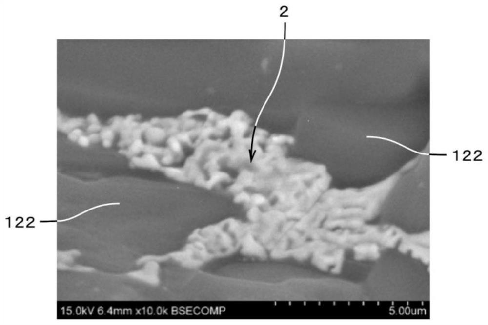
[0063] In embodiment 1, the CeO in material composition 2 and ZrO 2 The content ratios of are 6.1% by mass and 2.0% by mass, respectively. ZrO 2 The content rate of CeO 2 About 1 / 3 of the content rate. The content rate of the Ce-Zr containing particle 2 was 8.1 mass %. The solid solution rate of Zr was 17.2 mol%. The average particle diameter of the Ce—Zr-containing particles 2 was 55 nm. The oxygen storage capacity is as high as 0.0007.

Embodiment 2

[0064] In embodiment 2, the CeO in material composition 2 and ZrO 2 The content rates of and are 7.9% by mass and 2.6% by mass, respectively. ZrO 2 The content rate of CeO 2 About 1 / 3 of the content rate. The content of the Ce—Zr-containing particles 2 was 10.6% by mass. The solid solution rate of Zr was 18.3 mol%. The average particle diameter of the Ce—Zr-containing particles 2 was 120 nm. The oxygen storage capacity is as high as 0.0008.

Embodiment 3

[0065] In embodiment 3, the CeO in material composition 2 and ZrO 2 The content rates of and are respectively 9.6% by mass and 3.2% by mass. ZrO 2 The content rate of CeO 2 About 1 / 3 of the content rate. The content of the Ce—Zr-containing particles 2 was 12.9% by mass. The solid solution rate of Zr was 17.8 mol%. The average particle diameter of the Ce—Zr-containing particles 2 was 630 nm. The oxygen storage capacity is as high as 0.0007.


PUM

PropertyMeasurementUnit
thicknessaaaaaaaaaa
pore sizeaaaaaaaaaa
pore sizeaaaaaaaaaa

Abstract

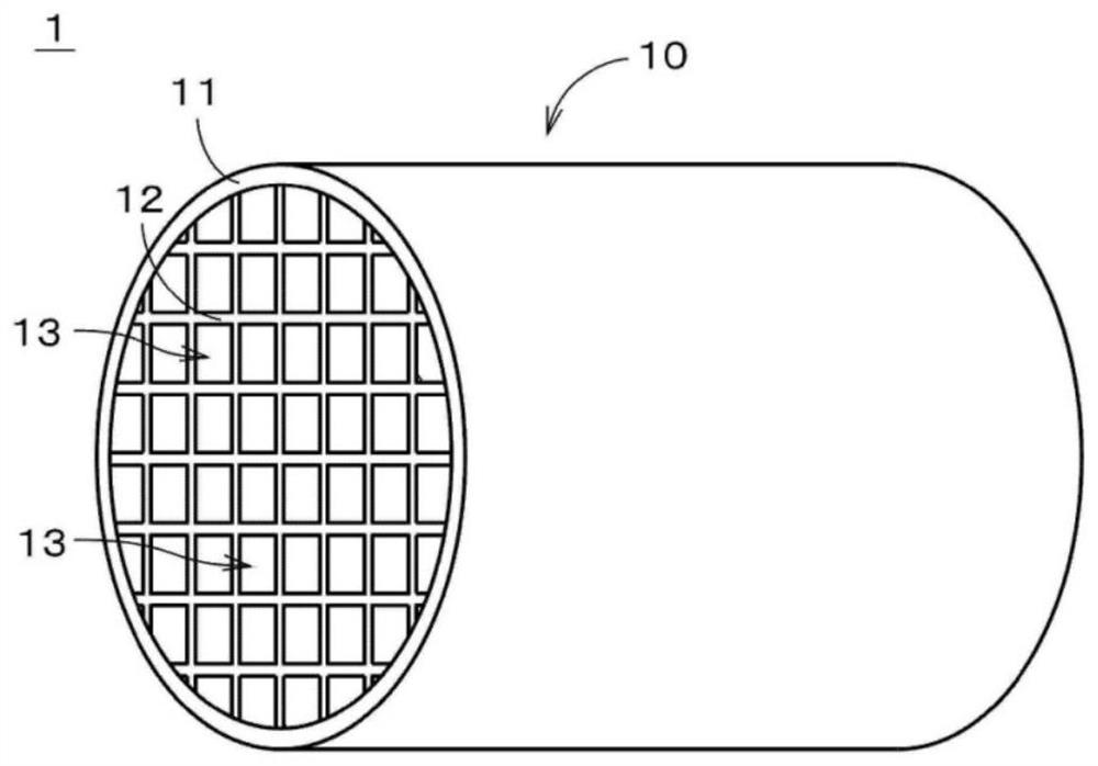
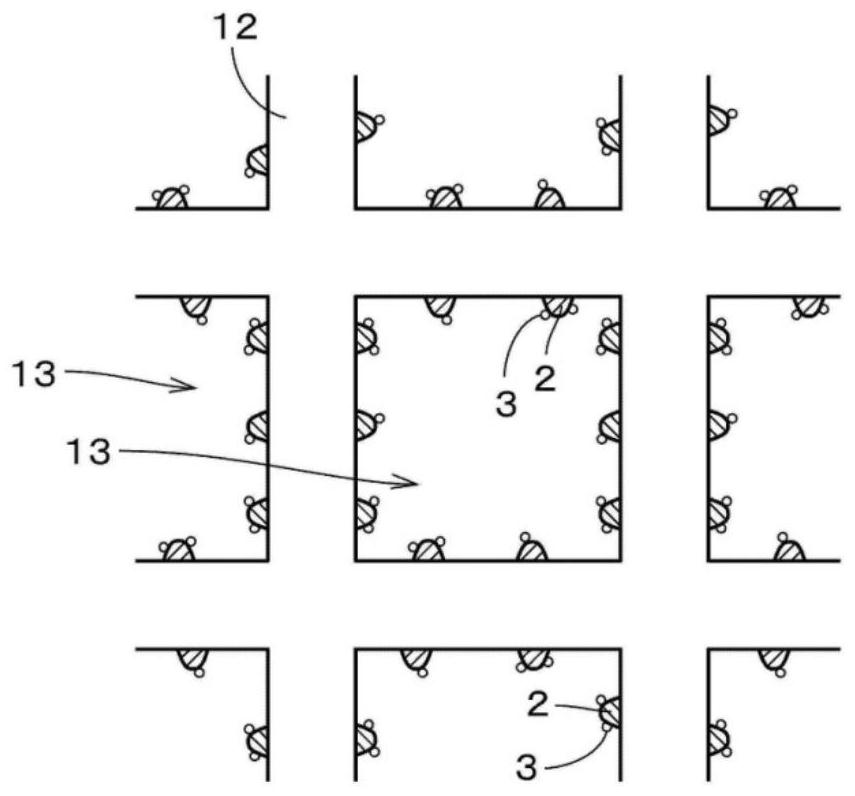
The invention provides a porous ceramic structure, and the co-catalysis capability of the porous ceramic structure is improved. A porous ceramic structure is provided with: a porous honeycomb structure (10), the main component of which is cordierite; and Ce-Zr-containing particles (2) that are fixed to the honeycomb structure (10). The Ce-Zr-containing particles (2) contain Ce and Zr. A Ce-Zr-containing particle (2) is provided with: a fixed part (21) positioned inside a honeycomb structure (10); and a protruding part (22) which is continuous with the fixed part (21) and protrudes from the honeycomb structure (10). As a result, the co-catalytic ability of the porous ceramic structure can be improved.

Description

technical field [0001] The present invention relates to porous ceramic structures. Background technique [0002] Conventionally, a porous ceramic structure having a honeycomb structure has been used as a catalytic converter in order to purify harmful substances such as HC, CO, and NOx contained in exhaust gas emitted from an engine of an automobile or the like. In such a porous ceramic structure, coating treatment such as γ-alumina is sometimes performed in order to increase the specific surface area and increase the catalyst loading amount, but the pressure loss may increase due to the coating treatment. Big. [0003] Therefore, Patent Document 1 proposes a technique of exposing a part of ceria particles on the pore surface of a honeycomb structure, and loading catalyst fine particles of a platinum group element on the ceria particles, thereby preventing The above-mentioned coating treatment is required. The ceria particles have oxygen storage and release capability, and...

Claims


Application Information

Patent Timeline
Patent Type & Authority Applications(China)
IPC IPC(8): C04B35/195C04B38/00B01J23/10B01J35/02B01D53/94B01D53/44B01D53/56B01D53/62
CPCC04B35/195C04B38/0006B01J23/10B01J35/023B01J23/002B01D53/945B01D2258/01B01D2257/40B01D2257/502C04B2235/3244C04B2235/3229C04B38/0009F01N3/2828F01N2330/06C04B2235/606C04B2235/3206B01J35/04C04B2111/0081C04B41/009C04B41/87C04B41/4547C04B41/4549C04B38/0096C04B41/5042C04B41/5045F01N2330/30C04B2235/3481
Inventor 泉有仁枝日高宪一三浦晃弘
Owner NGK INSULATORS LTD
Learn More