Cable connector and connector assembly

A cable connector and cable technology, which is applied to parts, connections, and fixed connections of connecting devices, can solve problems affecting product signal integrity, signal interference, etc., to save space on the motherboard, improve reliability, and reduce size. small effect

Pending Publication Date: 2022-03-04
AMPHENOL ELECTRONICS ASSEMBLY XIAMEN CO LTD
View PDF0 Cites 1 Cited by
  • Summary
  • Abstract
  • Description
  • Claims
  • Application Information

AI Technical Summary

Problems solved by technology

However, if the size of the connector is designed too short, it will cause signal interference between the upper and lower rows of terminal blocks, which will affect the signal integrity of the product

Method used


Image

  • Cable connector and connector assembly
  • Cable connector and connector assembly
  • Cable connector and connector assembly

Examples


Embodiment 1

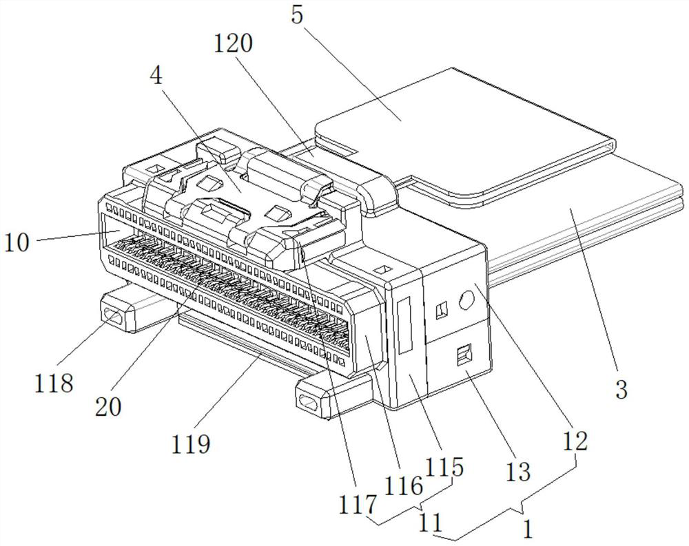
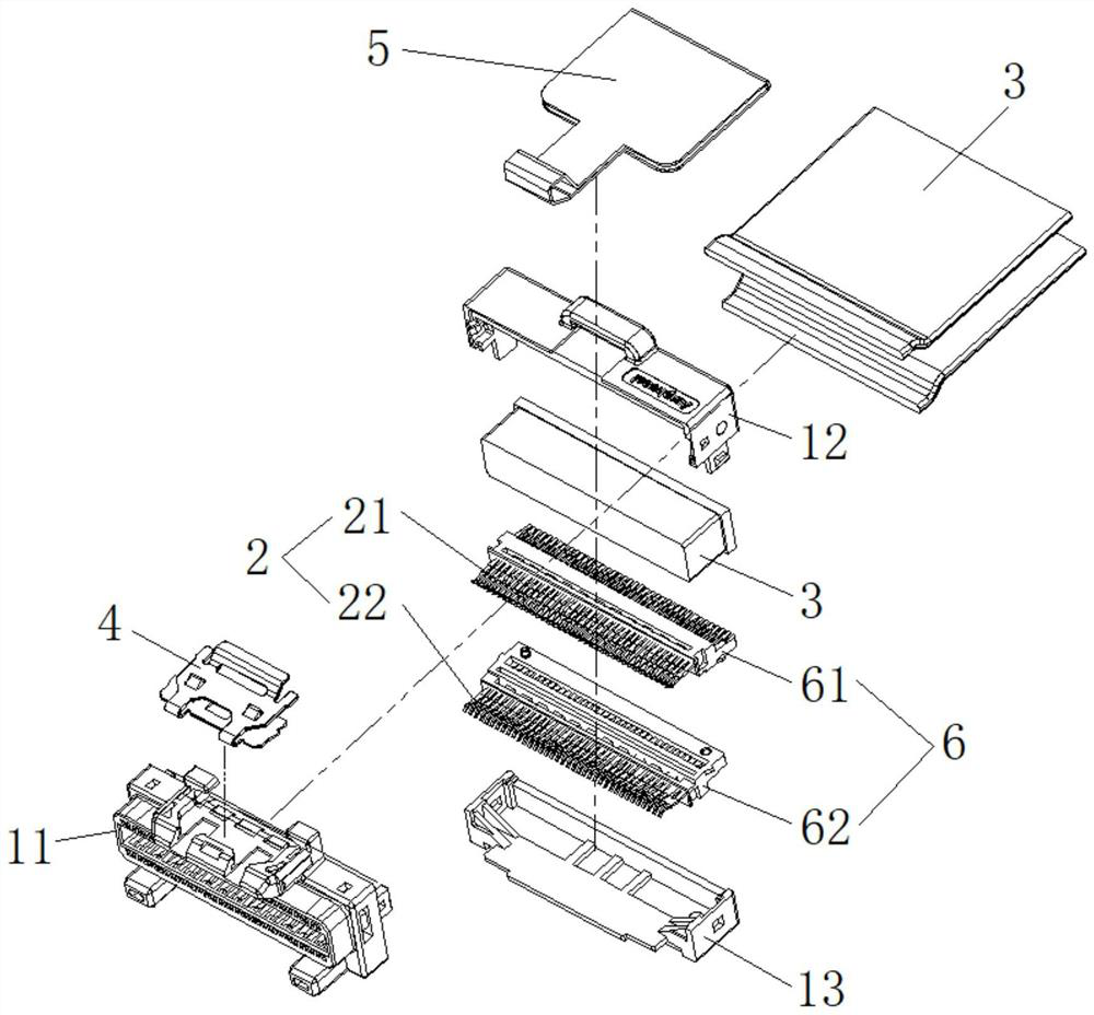
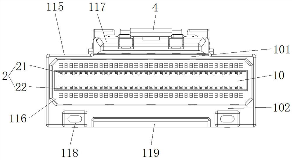
[0045] Figure 1-12As shown, a cable connector includes a housing 1, a conductive terminal group 2 disposed inside the housing 1, a cable 3 electrically connected to the conductive terminal group 2, and a locking member 4 installed on the top of the housing 1 And the drawstring 5 that is connected with the buckle 4. The front end of the housing 1 is provided with a socket slot 10, and the conductive terminal group 2 includes a first terminal row 21 and a second terminal row 22 symmetrically arranged on the upper and lower sides of the socket slot 10, and the first terminal row 21 and the second terminal row 22 are composed of several conductive terminals 20 arranged along the width direction of the socket slot 10 . The conductive terminal 20 includes a main body 201, a contact portion 202 bent from the front end of the main body 201, and a welding portion 203 extending backward from the rear end of the main body 201. The welding portion 203 of the first terminal row 21 and th...

Embodiment 2

[0055] Such as Figure 13 , Figure 14 As shown, a connector assembly includes a cable connector and a board connector 8, and the cable connector is the cable connector in the first embodiment. The board end connector 8 includes an insulating body 81 , a tongue 82 fixed inside the insulating body 81 for contacting and mating with the conductive terminal group of the cable connector, and a shell 83 sleeved outside the insulating body 81 . Preferably, the bottom of the housing 83 is bent to form a limiting groove 830 , and the limiting block 119 at the front end of the housing 1 of the cable connector is inserted into the limiting groove 830 for positioning.

[0056] In this embodiment, the thickness of the tongue 82 of the board end connector 8 is 2 mm, and the minimum distance h between the contact portion 202 of the first terminal row 21 of the cable connector and the contact portion 202 of the second terminal row 22 is 1.4 mm. ~2 mm, and the distance H between the welding ...


PUM


Abstract

The invention discloses a cable connector. The cable connector comprises a shell, a conductive terminal set arranged in the shell and a cable electrically connected with the conductive terminal set. The front end of the shell is provided with a plug-in groove, the conductive terminal group comprises a first terminal strip and a second terminal strip which are symmetrically arranged on the upper side and the lower side of the plug-in groove, and the first terminal strip and the second terminal strip are both composed of a plurality of conductive terminals. Each conductive terminal comprises a main body part, a contact part formed by bending from the front end of the main body part, and a welding part formed by extending backwards from the rear end of the main body part; and the welding part of the first terminal row and the welding part of the second terminal row are arranged in parallel. And the distance between the welding part of the first terminal strip and the welding part of the second terminal strip is 1-2.5 times of the minimum distance between the contact part of the first terminal strip and the contact part of the second terminal strip. The cable connector provided by the invention can avoid signal interference between the terminal strips to the greatest extent while meeting the requirement of low size, thereby ensuring the signal integrity of a product.

Description

technical field [0001] The invention relates to the technical field of connectors, in particular to a cable connector and a connector assembly. Background technique [0002] The traditional use of PCB to transmit signals has more and more limitations, because the PCB attenuates greatly when it is in use, which affects the signal integrity, so it is necessary to use connectors to reduce the attenuation. The currently used connector products usually have the problem of high height and are not suitable for use around the server chip. Therefore, it is necessary to develop a low-profile connector that can be placed under the heat sink to make full use of the space on the server motherboard. However, if the size of the connector is designed too short, it will cause signal interference between the upper and lower rows of terminal blocks and affect the signal integrity of the product. Therefore, it is imperative to develop a connector product that can not only meet the low-profile ...

Claims


Application Information

Patent Timeline
Patent Type & Authority Applications(China)
IPC IPC(8): H01R13/502H01R13/506H01R13/405H01R13/631H01R13/639H01R12/63H01R12/71
CPCH01R13/502H01R13/506H01R13/631H01R13/639H01R13/405H01R12/716H01R12/63
Inventor 杨文初唐辉柯英豪刘振兴李杭
Owner AMPHENOL ELECTRONICS ASSEMBLY XIAMEN CO LTD
Why Eureka
Try Eureka