
Back-to-back multiple excitation hybrid generator based on homodromous electromagnetic pole coupling

An electrical excitation and generator technology, applied in the magnetic circuit, motor, magnetic circuit and other directions characterized by magnetic materials, can solve the problem of uneven distance between the three-phase winding coil and the permanent magnet, achieve the advantage of heat dissipation and reduce the complexity , the effect of improving the magnetic utilization rate

Pending Publication Date: 2022-03-04
WOLONG ELECTRIC NANYANG EXPLOSION PROTECTION GRP CO LTD +1
View PDF2 Cites 0 Cited by
  • Summary
  • Abstract
  • Description
  • Claims
  • Application Information

AI Technical Summary

Problems solved by technology

[0005] The Chinese invention patent "a π-type hybrid excitation double-salient motor" (publication number: CN108808895A) discloses a π-type hybrid excitation double-salient motor, including: a stator and a rotor, the stator and the rotor are arranged coaxially, and the stator It includes 6 spliced ​​π-shaped stator core punches, and the permanent magnets and the iron core attached to the excitation winding are arranged at intervals between the 6 π-shaped stator core punches, and the excitation winding is wound on the attached iron core of the excitation winding. The armature windings are wound on the salient pole teeth of the stator core punching sheet; the π-type hybrid excitation double salient pole motor balances the electromagnetic characteristics of the three-phase windings and effectively reduces the torque ripple of the motor; although it uses electric excitation and permanent magnets Excitation hybrid excitation method, but it solves the problem of uneven distance between all coils of the three-phase winding and the permanent magnet

Method used


Image

  • Back-to-back multiple excitation hybrid generator based on homodromous electromagnetic pole coupling
  • Back-to-back multiple excitation hybrid generator based on homodromous electromagnetic pole coupling
  • Back-to-back multiple excitation hybrid generator based on homodromous electromagnetic pole coupling

Examples


Embodiment Construction

[0034] The implementation of the present invention will be illustrated by specific specific examples below, and those skilled in the art can easily understand other advantages and effects of the present invention from the contents disclosed in this specification.

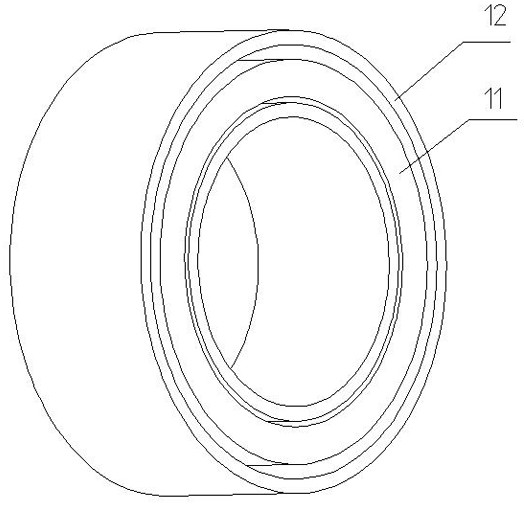
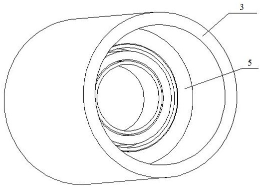
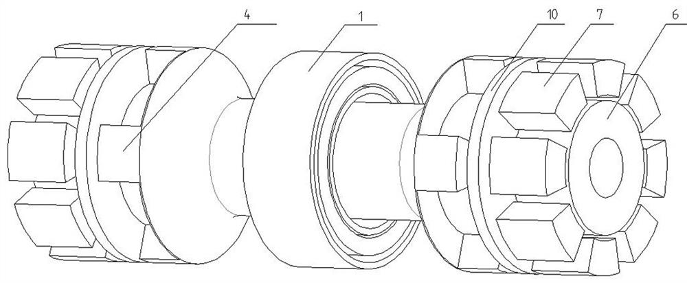
[0035] The present invention provides a back-to-back multiple excitation hybrid generator based on electromagnetic pole coupling in the same direction, such as Figure 1 to Figure 8 shown.

[0036] The back-to-back multi-excitation hybrid generator based on electromagnetic pole coupling in the same direction includes electric excitation parts and permanent magnet power generation parts arranged back to back, and the permanent magnet power generation parts are symmetrically arranged at both ends of the electric excitation part;

[0037] The electric excitation part includes an electric excitation source 1, a magnetic bridge rotor 2 and a magnetic bridge housing 3, and the electric excitation source 1 is coaxially sle...


PUM


Abstract

According to the back-to-back multiple excitation hybrid generator based on homodromous electromagnetic pole coupling, the electric excitation part and the permanent magnet power generation parts are arranged back to back, and the permanent magnet power generation parts are symmetrically arranged at the two ends of the electric excitation part, so that the structures of the electric excitation part and the permanent magnet power generation parts and the overall layout of the electric excitation part and the permanent magnet power generation parts are optimized; the magnetic efficiency and the magnetic utilization rate of electric excitation are improved, and the characteristics of high power density and excellent electric output characteristic are realized; and meanwhile, in cooperation with related power electronic means, the system cost can be greatly reduced, the overall efficiency is improved, the system is more suitable for being applied to related occasions such as aerospace, and the applicability of the structure is improved.

Description

technical field [0001] The invention belongs to the technical field of generators, in particular to a back-to-back multiple excitation hybrid generator based on co-directional electromagnetic pole coupling. Background technique [0002] The permanent magnet and electric excitation hybrid generator structure has the advantages of wide adjustable output voltage range and flexible control variable coordination, and can be widely used in various fields such as aviation industry, high-speed generators, electric vehicles, and traction transportation. [0003] The combined structure of permanent magnet and electric excitation is the core part of this type of generator, which mainly involves permanent magnet structure design, electromagnetic structure design and corresponding magnetic circuit design. Different electromagnetic circuits and mechanical structures will lead to different performances of motors, as well as different reliability and maintainability. A reasonable structura...

Claims


Application Information

Patent Timeline
Patent Type & Authority Applications(China)
IPC IPC(8): H02K16/00H02K1/278H02K1/24H02K1/12H02K1/02
CPCH02K16/00H02K1/278H02K1/24H02K1/12H02K1/02H02K2213/03Y02T10/64
Inventor 刘建波张浩周少正邢印刘玉宝曹海坡范红伟付晓张虎赵现伟孙毅
Owner WOLONG ELECTRIC NANYANG EXPLOSION PROTECTION GRP CO LTD
Learn More