
Processing machine tool for printing mold

A technology for processing machine tools and molds, applied in the field of mold machine tool equipment, can solve the problems of difficult printing mold errors, low production efficiency, and difficulty in ensuring product yield, and achieve the effect of reducing deviation and defective products and facilitating cycle rotation

Pending Publication Date: 2022-03-08
王洋
View PDF6 Cites 0 Cited by
  • Summary
  • Abstract
  • Description
  • Claims
  • Application Information

AI Technical Summary

Problems solved by technology

[0003] The existing printing mold is in the shape of a ring and is equipped with a plurality of equidistant inner notches. However, in the existing production process, the printing mold is often manually bent and forged, and the production efficiency is low. It is difficult to perform multiple repeated bending operations, which makes it difficult to control the error generated by the printing mold formed by bending and rolling, making it difficult to ensure the yield of the product

Method used


Image

  • Processing machine tool for printing mold
  • Processing machine tool for printing mold
  • Processing machine tool for printing mold

Examples


Embodiment Construction

[0026] In order to make the purpose, technical solutions and advantages of the embodiments of the present invention clearer, the technical solutions in the embodiments of the present invention will be clearly and completely described below in conjunction with the drawings in the embodiments of the present invention. Obviously, the described embodiments It is a part of embodiments of the present invention, but not all embodiments. The components of the embodiments of the invention generally described and illustrated in the figures herein may be arranged and designed in a variety of different configurations. Accordingly, the following detailed description of the embodiments of the invention provided in the accompanying drawings is not intended to limit the scope of the claimed invention, but merely represents selected embodiments of the invention. Based on the embodiments of the present invention, all other embodiments obtained by persons of ordinary skill in the art without cre...


PUM


Abstract

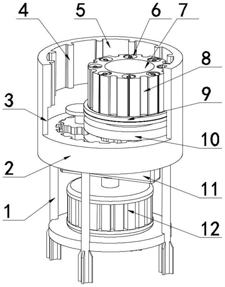
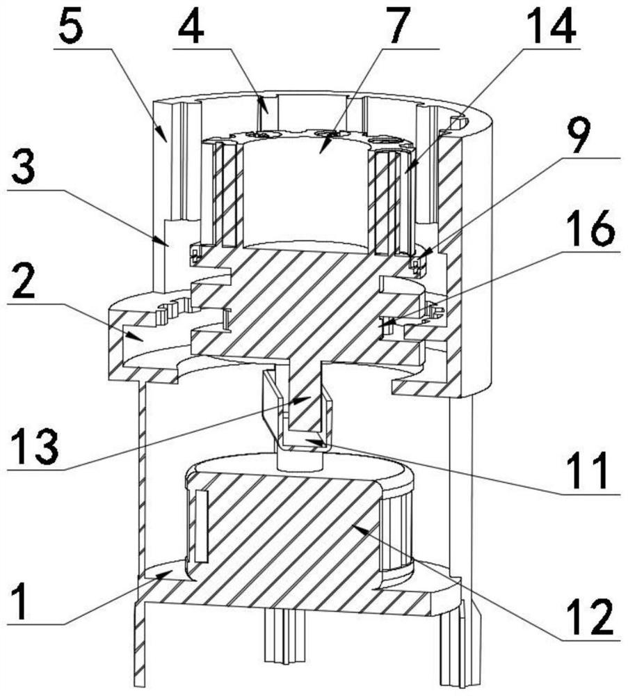
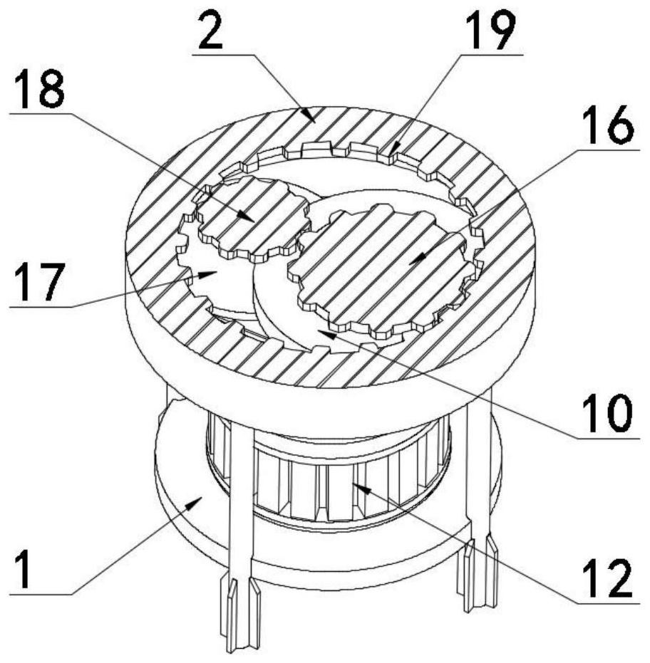
The machine tool comprises a supporting rack and an annular groove shell fixedly installed on the supporting rack, an opening vertical shell is fixedly arranged on the outer edge of the upper portion of the annular groove shell, a forming side shell is fixedly arranged at the top end of the opening vertical shell, and at least two convex opening molds are arranged on the inner wall of the forming side shell; a first abutting ring and a second abutting ring abut against an inner cavity of the annular groove shell, a second rotating rod is fixedly arranged at the axis of the first abutting ring, a first rotating rod is fixedly arranged at the axis of the second abutting ring, and the top end of the top ring abuts against the bottom end of the forming side shell. According to the invention, a double-turntable rolling forming structure is adopted to realize one-time rolling mold forming processing when the rolling mold rotates in the forming side shell, and a double-turntable abutting transmission structure is adopted to realize that the driving pair rotates to drive the rolling mold to abut against and rotate in the inner cavity of the forming side shell, so that the circulating rotation of the rolling mold is facilitated; and an elastic sheet type annular self-cutting separation structure is adopted, so that circulating rolling production of the printing mold is realized.

Description

technical field [0001] The invention belongs to the technical field of mold machine tools, in particular to a processing machine tool for printing molds. Background technique [0002] Mold, various molds and tools used in industrial production for injection molding, blow molding, extrusion, die-casting or forging forming, smelting, stamping and other methods to obtain the required products. It is a piece of flat paper. After printing, to make a box, you need to make a flat mold that is the same as the box for stamping. This mold is a printing die, which can also be referred to as a die or die. [0003] The existing printing mold is in the shape of a ring and is equipped with a plurality of equidistant inner notches. However, in the existing production process, the printing mold is often manually bent and forged, and the production efficiency is low. It is difficult to perform multiple repeated bending operations in the process, which makes it difficult to control the error ...

Claims


Application Information

Patent Timeline
Patent Type & Authority Applications(China)
IPC IPC(8): B21D35/00B21D37/08B21D28/14B21D45/04
CPCB21D35/002B21D37/08B21D28/14B21D45/04
Inventor 王洋
Owner 王洋
Learn More