

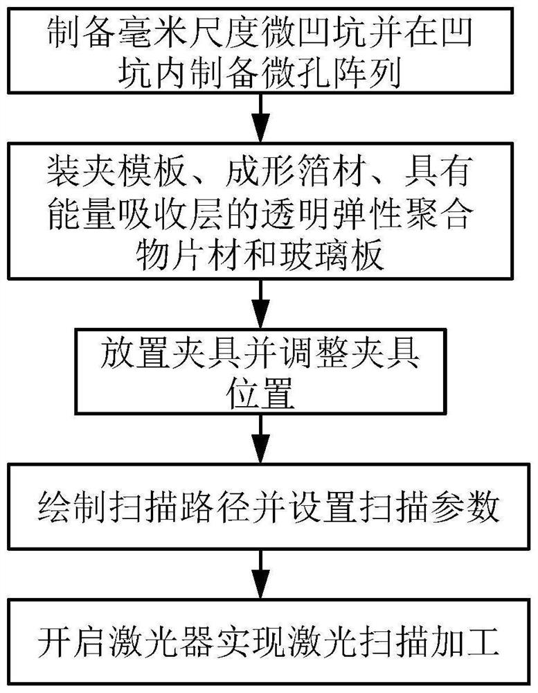
Laser shock forming method for compound eye-like double-scale curved surface structure surface
A curved surface structure and laser shock technology, which is applied in laser welding equipment, welding equipment, metal processing equipment, etc., can solve problems such as difficult forming, and achieve the effect of reducing the stroke and making mold preparation convenient and fast
- Summary
- Abstract
- Description
- Claims
- Application Information
AI Technical Summary
Problems solved by technology
Method used
Image

Examples
Embodiment 1
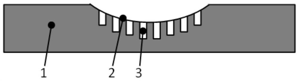
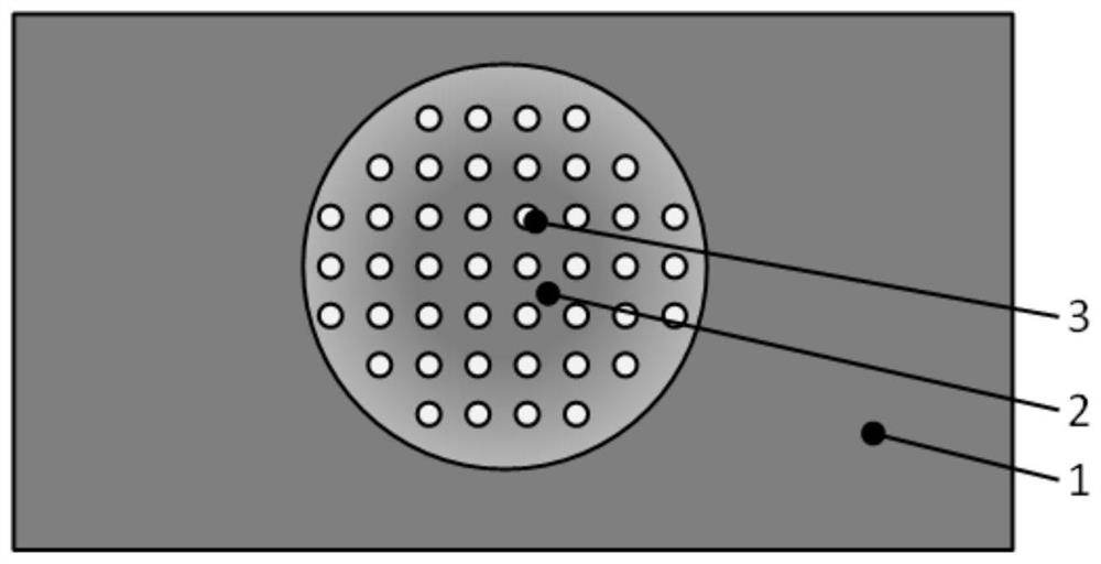
[0059] Example 1 (the forming foil is made of aluminum foil with a thickness of 10 μm, the millimeter-scale curved surface on the mold steel plate is a laser direct writing surface, the micron-scale structure is a laser scanning induced processing structure, the thickness of the glass plate is 5mm, and the laser energy absorption layer material is industrial Black paint with a thickness of about 50 μm. The elastic polymer sheet is a polydimethylsiloxane (PDMS) sheet with a thickness of 3 mm. The laser processing system is a nanosecond fiber laser marking machine with a wavelength of 1064 nm. The laser pulse width 300ns)
[0060] The laser direct writing method was used to prepare Ф5mm pits on the surface of the 7mm thick mold steel, and the micropore array was prepared in the water environment by laser scanning to induce micropores (Applied Surface Science 462 (2018) 847–855). Afterwards, the surface of the mold steel is ground and polished to remove surface spatter. Install ...
Embodiment 2
[0061] Example 2 (the forming foil is made of aluminum foil with a thickness of 10 μm, the millimeter-scale curved surface on the mold steel plate is a laser direct writing surface, the micron hole array template foil is a Ф5 mm copper mesh purchased on the market, and the diameter of the copper mesh is 30 μm. The thickness of the glass plate is 5 mm, the material of the laser energy absorbing layer is industrial black paint, the thickness is about 50 μm, the elastic polymer sheet is a polydimethylsiloxane (PDMS) sheet with a thickness of 3 mm, and the laser processing system has a wavelength of 1064nm nanosecond fiber laser marking machine, laser pulse width is 300ns)
[0062] The pits of Ф3mm were prepared on the surface of 7mm thick die steel by laser direct writing process. Afterwards, the surface of the mold steel is ground and polished to remove surface spatter. The mold steel plate, the micro-hole array foil, the formed aluminum foil, the polydimethylsiloxane (PDMS) sh...
PUM
| Property | Measurement | Unit |
|---|---|---|
| thickness | aaaaa | aaaaa |
| diameter | aaaaa | aaaaa |
| thickness | aaaaa | aaaaa |
Abstract
Description
Claims
Application Information