Electrochemical based processing device and method

A processing device, electrochemical technology, applied in the direction of current conduction device, additive processing, metal processing equipment, etc., can solve the problems that affect the forming accuracy of the model, the machining accuracy cannot be guaranteed, and the workpiece accuracy is limited, so as to reduce production costs and equipment volume, avoid repeated electrodeposition, and achieve the effect of molding processing

Active Publication Date: 2022-04-19
YUANZHI TECH SHANGHAI CO LTD
View PDF12 Cites 0 Cited by
  • Summary
  • Abstract
  • Description
  • Claims
  • Application Information

AI Technical Summary

Problems solved by technology

Even if the electrolytic transfer process is used, it is still necessary to make a targeted pattern mask (tool cathode), which is less flexible
[0004] The existing electrodeposition or electroetching technology generally needs to make a closed cavity for electrolyte pumping to achieve the purpose of rapid renewal. The process is cumbersome and consumes a relatively large amount of electrolyte, and the existing technology is not suitable for the formation of multi-layer three-dimensional structures.
The existing technology uses programmable electrode arrays for electrolytic machining, either there is a problem that the machining accuracy cannot be guaranteed, or there is a problem that the ability to conduct current is limited and the molding speed is affected, and the sensitivity to current on-off control needs to be improved
If the traditional selective electrodeposition method is used, that is, the nozzle is used to spray electrolyte (or ionic liquid, or ionic solution) and energized for electrodeposition to form metal parts by layer-by-layer deposition, the process and the structure of the device are still relatively complicated. Due to the use of a movable nozzle or multiple array electrodes, the number is limited and the accuracy of the workpiece is limited. Not only is the printing speed slow, but also the electrolyte covers the entire model surface during the electrodeposition process, and the entire surface of the model will be damaged during the electrodeposition process. Electrodeposition occurs, affecting the molding accuracy of the model

Method used


Image

  • Electrochemical based processing device and method
  • Electrochemical based processing device and method
  • Electrochemical based processing device and method

Examples


Embodiment 1

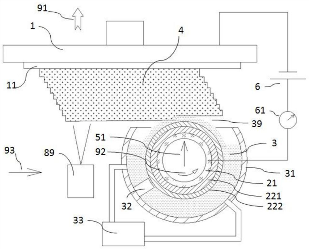
[0060] image 3 It is shown that the photoconductive conductive layer 22 of the photoelectric wheel 2 adopts a PN junction. The photoconductive conductive layer 22 is composed of an inner N-type semiconductor layer 221 and an outer P-type semiconductor layer 222, wherein the N-type semiconductor layer 221 is bonded to the transparent conductive layer 21, and the P-type semiconductor layer 222 is bonded to the ionic liquid. 3 Electrical connection, such as contact, can also be provided with a conductive protective layer on the surface of the P-type semiconductor layer 222, through which the protective layer is in contact with the ionic liquid 3 to realize connection and electrical conduction. Of course, the conductive protective layer is preferably arranged in an array. In order to prevent the diffusion of current in the protective layer from affecting the precision of electrochemical machining. The P-type semiconductor layer 222 can also be arranged in a tiny array. Accordin...

Embodiment 2

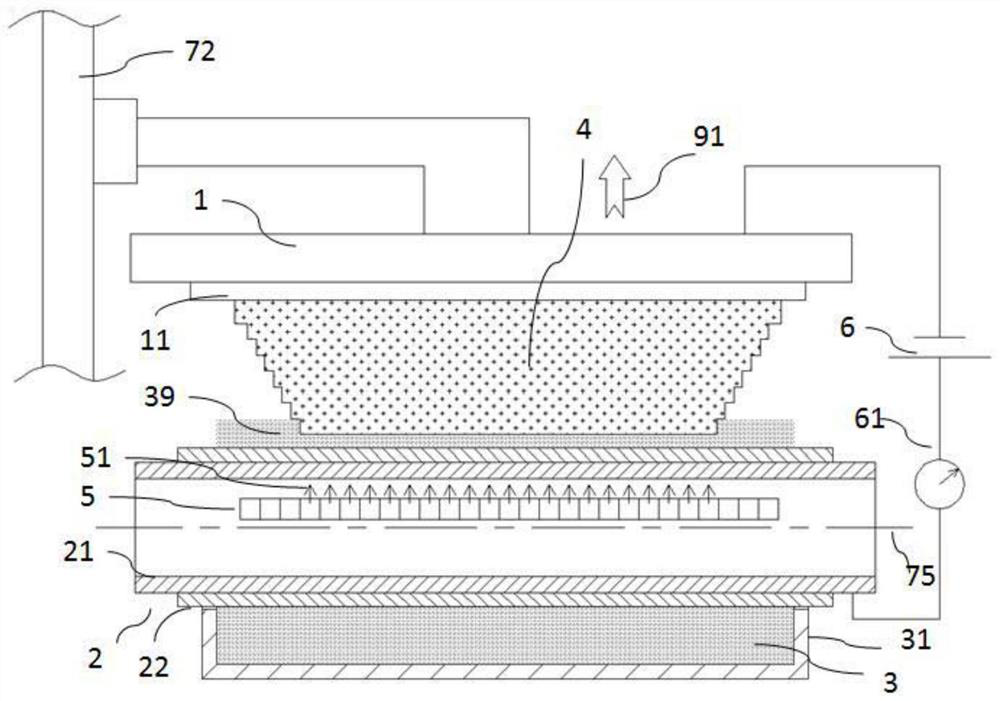
[0063] Figure 4 It is shown that the photoelectric wheel 2 can adopt a conveyor belt structure that rotates in circles. The photoelectric wheel 2 at least composed of the transparent conductive layer 21 and the light control conductive layer 22 can be made of elastic material, and supported by at least two rollers 81 to form a tape-and-roll structure. This conveyor belt photoelectric wheel 2 can certainly also be opened (one part is disconnected), and the two ends of the conveyor belt photoelectric wheel 2 can be wound on a roller 81 at one end, and the other end is wound on another roller 81 and supported by at least two rollers 81 to form a tape-and-roll structure. Each roller 81 rotates in the same direction to drive the conveyor belt photoelectric wheel 2 to rotate along the first arrow 92, so that the part of the photoelectric wheel 2 between the two rollers 81 has a flat surface, allowing more light beams 51 to irradiate the photoelectric conductive layer 22. Form lar...

Embodiment 3

[0065] Figure 5 and Image 6 It shows that multiple photoelectric wheels 2 can be used to conduct electrodeposition at the same time, so as to increase the electrodeposition speed or realize electrodeposition of composite materials. E.g, Figure 5 It shows that two photoelectric wheels 2 are arranged in front and back. The front photoelectric wheel 2-1 electrodeposits layer A, and the rear photoelectric wheel 2-2 continues to deposit the next layer of material on the basis of layer A, so that two layers can be realized at the same time. Electrodeposition can increase the speed of electrodeposition forming.

[0066] Image 6 In , two photoelectric wheels 2 are illustrated electrodepositing different materials so that a deposition model 4 with composite materials (heterogeneous materials) can be formed. For example, photoelectric wheel 2-1 electrodeposits material A to form part A 4-1 in deposition model 4, photoelectric wheel 2-2 electrodeposits material B to form part B 4...


PUM


Abstract

The invention relates to an electrochemical-based processing device and method, including a forming platform, a power supply and at least one forming mechanism, the forming mechanism is arranged below the forming platform and can move relatively with the forming platform, and the forming mechanism includes a photoelectric wheel, a light source and an ionic liquid tank. The ionic liquid is stored in the ionic liquid tank. The photoelectric wheel can be rotated and partially immersed in the ionic liquid. The photoelectric wheel includes an inner transparent conductive layer and an outer light-controlled conductive layer that are combined with each other. The transparent conductive layer and the One pole of the power supply is electrically connected, and the forming platform is electrically connected to the other pole of the power supply. The light source is arranged inside the photoelectric wheel and the light beam emitted by the light source can selectively illuminate the photoelectric wheel in the direction of the forming platform. The present invention can realize flexible and accurate selective electrodeposition additive manufacturing or selective electrolytic etching, can comprehensively improve the precision, efficiency and control sensitivity of electrochemical deposition additive or electrolytic etching, is beneficial to reduce costs, and is convenient for complex and large-scale manufacturing. Production of area 3D models.

Description

technical field [0001] The invention belongs to the technical field of electrodeposition and electroetching, in particular to an electrochemical-based processing device and method. Background technique [0002] In the existing electrochemical deposition, micro-electroforming or electrolysis process, the process is relatively complicated and the cost is high, and there are generally problems of lack of flexibility and insufficient precision. [0003] For example, in the process of electroforming, it is usually necessary to customize anodes, and different models of electroforming need to customize different anodes, which is costly and time-consuming for a small number of models. Typical electrolytic processing, such as mask electrolysis, requires multi-step processes such as gluing, exposure, and development of the anode, which is time-consuming, laborious, and costly. Similarly, different anode mask patterns need to be customized for different processing patterns. Even if t...

Claims


Application Information

Patent Timeline
Patent Type & Authority Patents(China)
IPC IPC(8): C25D5/02C25D17/02C25D21/00C25F3/02C25F7/00B33Y10/00B33Y30/00B33Y40/00
CPCC25D5/02C25D17/02C25D17/007C25D21/00C25F3/02C25F7/00B33Y10/00B33Y30/00B33Y40/00C25D17/001C25D3/665C25D21/18C25D5/024C25D5/06B29C64/124B29C64/218C25D1/003H01L27/1446H01L27/1443B33Y80/00B33Y70/10
Inventor 季鹏凯
Owner YUANZHI TECH SHANGHAI CO LTD
Why Eureka
Try Eureka