Bagged cement unloading robot

A robot and cement technology, applied in loading/unloading, manipulators, conveyors, etc., can solve the problems of limited strength of packaging bags, small size of cement powder, dust, etc., to achieve good suction and collection effect, uniform contact surface, guarantee The effect of air quality

Active Publication Date: 2022-03-08
HEFEI CEMENT RES DESIGN INST
View PDF9 Cites 0 Cited by
  • Summary
  • Abstract
  • Description
  • Claims
  • Application Information

AI Technical Summary

Problems solved by technology

[0003] The existing robot for bagged cement unloading usually uses a transmission mechanism to transport the bagged cement on the car to the bottom, and the robot drives multiple sets of grippers to control the bagged cement, and the installation device The intelligent palletizing is completed according to the program, but the amount of cement powder in the bagged cement is not completely filled, which makes the cement powder in the bag unevenly distributed. During the unloading process, the bagged cement is unevenly distributed due to the internal cement powder The volume of cement is irregular. When unloading and stacking after clamping, the actual stacking of bagged cement with uneven volume is unstable. As the stacking height increases, the stacked bagged cement is prone to tipping and rollover. , and the current unloading robot is difficult to adjust effectively, and the use effect is not good
[0004] On the other hand, the existing unloading robot for bagged cement is easy to be scratched and broken during transportation and handling due to the limited strength of the bagged cement packaging bag during use, and the volume of cement powder inside It is very small, and a large amount of cement powder is attached to the surface of the packaging bag. Under the impact and vibration, the cement powder on the surface of the bagged cement is easy to scatter and rise. In fact, when the unloading robot clamps and stacks, the falling When the bagged cement collides with the bagged cement at the bottom, there will be relatively serious dust emission, which will reduce the environmental quality of the unloading site, and the surface of the unloading robot is heavily dusted, and the use effect is not good.

Method used


Image

  • Bagged cement unloading robot
  • Bagged cement unloading robot
  • Bagged cement unloading robot

Examples


no. 1 example

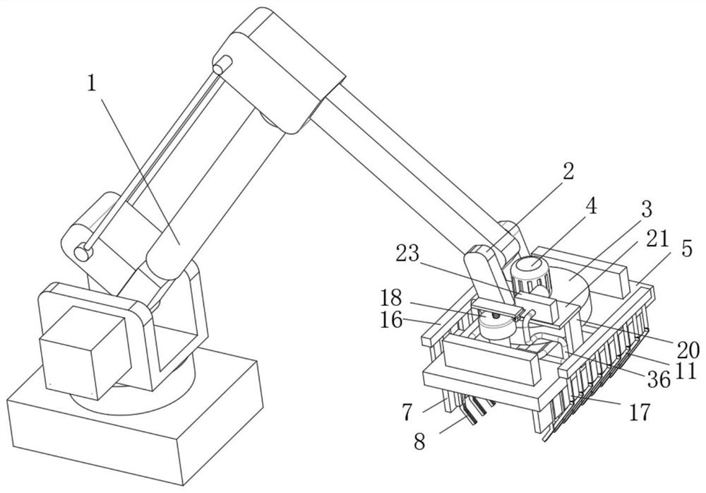
[0039] The first embodiment: as figure 1 , figure 2 , Figure 5 , Image 6 , Figure 7 with Figure 8 As shown, when unloading and stacking, the main body of the robot 1 moves so that the base 5 is close to the bagged cement downwards, and the existing pneumatic control box on the top surface of the mounting seat 3 is used to push the existing pneumatic control box to push the The angle of movement of the control clip 6 swings, so that the control clips 6 on both sides drive the installation plate 7 to swing, and then the bottoms of the jaws 8 installed on both sides are moved closer and tilted to hold the bagged cement from the bottom of the bagged cement, so that the jaws 8 are tilted Clamp the side of the bagged cement, and keep the bagged cement at the top of the side of the jaw 8, complete the clamping, start the power motor 22, so that the power motor 22 drives the rotating shaft 24 to rotate, and at the same time make the cam 25 on the outer surface of the rotating...

no. 2 example

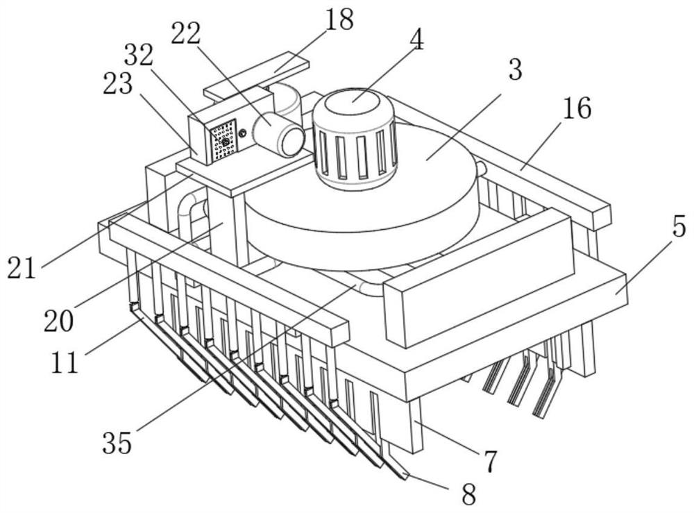
[0046] The second embodiment: as figure 1 , image 3 , Figure 4 , Figure 8 with Figure 9 As shown, when the robot grabs bagged cement, while the power motor 22 drives the rotating shaft 24 to rotate, the second gear 30 on the outer surface of the rotating shaft 24 drives the first gear 28 on the outer surface of the mounting shaft 27 to rotate, which is relatively The larger No. 2 gear 30 drives the smaller No. 1 gear 28 to rotate at a high speed. With the high-speed rotation of the No. 1 gear 28, the installation shaft 27 drives the blade 29 to rotate, and then the air inside the No. 3 pipe 36 is sucked into the fixed box 23, As the power motor 22 rotates, multiple sets of swing rods 11 beat the bagged cement repeatedly, so that the auxiliary cement powder on the surface of the bagged cement vibrates and is sucked into two sets of suction sleeves 34 through the suction holes 33, and rotates with the blades 29. Air is sucked, and the cement powder in the two sets of suc...

no. 3 example

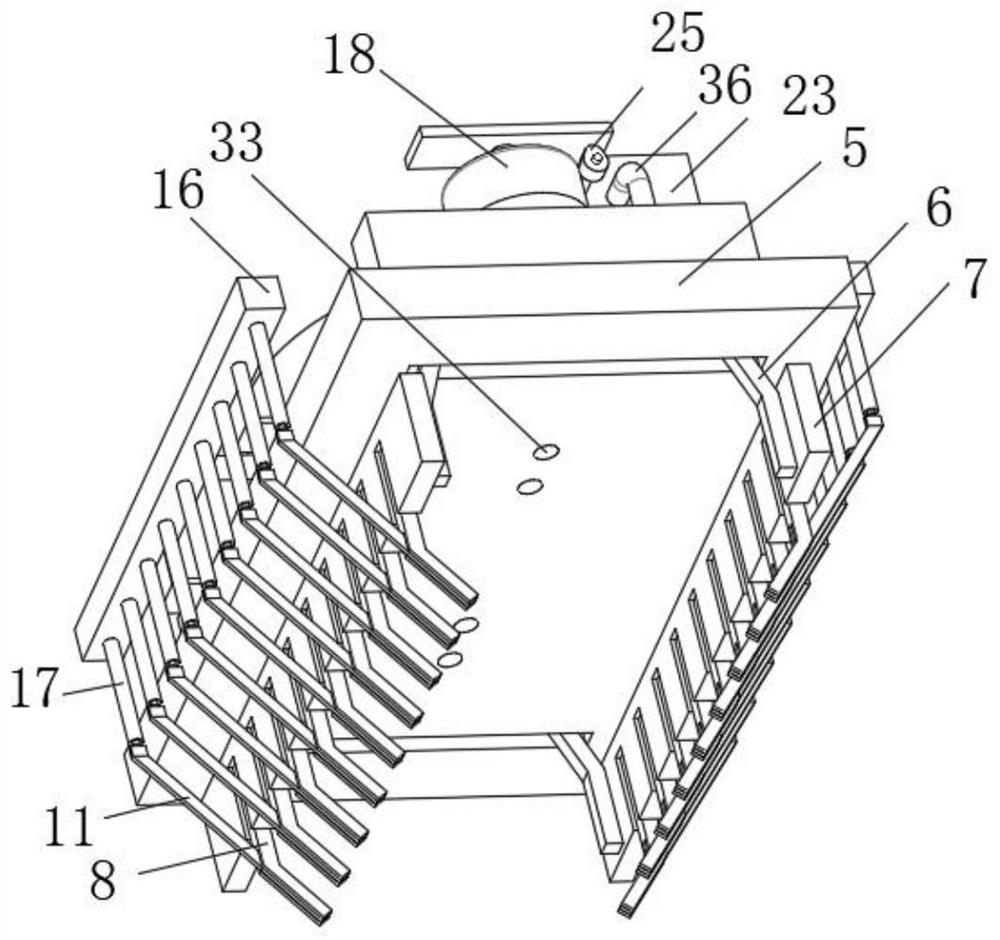
[0051] The third embodiment: as figure 1 , Figure 4 , Figure 8 with Figure 9 As shown, after the cement powder is gradually sucked in the fixed box 23, the robot completes the unloading work, and the locking cap 324 is unscrewed from the fixed rod 321 from the side of the fixed box 23, and the filter plate 323 is taken off outwardly. Manually sweep the cement powder on the filter hole of the filter plate 323 and the side into the external storage box, and gently sweep out the cement powder in the fixed box 23 through the installation port 31 on the side of the fixed box 23, and sweep it out The cement powder is placed in the storage box, and the cleaning and cleaning are completed.

[0052] First, use the power motor 22 to drive the rotation shaft 24 to rotate, so that the cam 25 rotates, and the second gear 30, which has a number of teeth much larger than the number of teeth of the first gear 28, drives the first gear 28 to rotate, so that the first gear 28 drives the i...


PUM


Abstract

The invention belongs to the technical field of unloading robots, and discloses a bagged cement unloading robot which comprises a robot body, a connecting frame, a mounting seat, a control motor and a base, a control clamp is movably mounted on the bottom surface of the base, and a mounting plate is fixedly mounted on the side surface of the control clamp. The swing rod partially sleeved with the side groove can swing around the fixed shaft, the vibration hydraulic mechanism and the power motor are additionally distributed on the top of the base, vertical vibration of a push plate of the vibration hydraulic mechanism is effectively achieved through the power motor, and the push mechanism repeatedly pushes the swing rod to swing through changes of hydraulic oil; bagged cement is effectively and evenly flapped and pushed through the multiple sets of swing rods evenly distributed below the bagged cement, then the bagged cement is evenly distributed in packaging bags, it is guaranteed that the contact faces between every two sets of bagged cement are even and flat in the stacking process, the stacking stability is improved, and the actual unloading effect is improved.

Description

technical field [0001] The invention belongs to the technical field of unloading robots, in particular to a robot for unloading bags of cement. Background technique [0002] A robot is an intelligent machine that can work semi-autonomously or fully autonomously. At present, international robotics scholars divide robots into two categories from the application environment: industrial robots in manufacturing environments and service and humanoid in non-manufacturing environments. Industrial robots are divided into four types according to the movement form of the arm. The arm of the rectangular coordinate type can move along three rectangular coordinates; the arm of the cylindrical coordinate type can be used for lifting, turning and telescopic movements; the arm of the spherical coordinate type can rotate, pitch and stretch; the arm of the joint type has multiple Rotary joints, when unloading bagged cement, robots are often used for convenient unloading. [0003] The existin...

Claims


Application Information

Patent Timeline
IPC IPC(8): B65G67/24B65G69/00B65G61/00B65G69/18B25J15/00
CPCB65G67/24B65G69/00B65G61/00B65G69/186B25J15/00B65G2201/0238
Inventor 范宗民吴玉辉
Owner HEFEI CEMENT RES DESIGN INST
Why Eureka
Try Eureka