Broadband circular polarization transmission array antenna based on dielectric structure
A medium structure, circularly polarized technology, applied to antenna unit combinations, antennas, antenna arrays, etc. with different polarization directions, it can solve the problems of insufficient axial ratio bandwidth and narrow axial ratio bandwidth, etc., and achieve high gain and wide axial ratio. Bandwidth and stable performance
- Summary
- Abstract
- Description
- Claims
- Application Information
AI Technical Summary
Problems solved by technology
Method used
Image

Examples
Embodiment
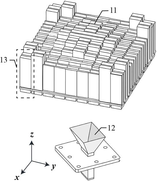
[0039] A broadband circularly polarized transmissive array antenna based on a dielectric structure, such as figure 1 As shown, it includes a transmission array surface 11 and a feed source 12;
[0040] Wherein, the transmission array surface 11 includes 8 types, multiple array elements 13 arranged in a linear form with different sizes; the feed source 12 is a broadband linearly polarized antenna;
[0041] The feed source 12 is located on the central axis of the transmission array surface 11 , illuminates the transmission array surface 11 vertically, and forms an angle of 45 degrees with the transmission array surface 11 in the horizontal direction.
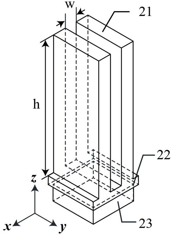
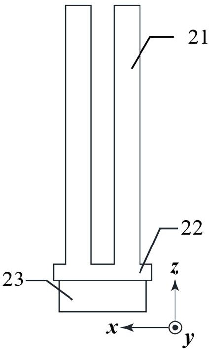
[0042] figure 2 and image 3 Shown are a full view and a side view of the front unit 13, respectively, and the front unit 13 includes a dielectric block 21, a support structure 22 and a matching structure 23 connected sequentially from top to bottom;
[0043] The dielectric block 21, the supporting structure 22 and the matching...
Embodiment 2
[0062] A broadband circularly polarized transmissive array antenna based on a dielectric structure, such as figure 1 As shown, it includes a transmission array surface 11 and a feed source 12;
[0063] Wherein, the transmission array surface 11 includes 8 types, multiple array elements 13 arranged in a linear form with different sizes; the feed source 12 is a broadband linearly polarized antenna;
[0064] The feed source 12 is located on the central axis of the transmission array surface 11 , illuminates the transmission array surface 11 vertically, and forms an angle of 45 degrees with the transmission array surface 11 in the horizontal direction.
[0065] figure 2 and image 3 Shown are a full view and a side view of the front unit 13, respectively, and the front unit 13 includes a dielectric block 21, a support structure 22 and a matching structure 23 connected sequentially from top to bottom;
[0066] The dielectric block 21, the supporting structure 22 and the matchi...
Embodiment 3
[0070] A broadband circularly polarized transmissive array antenna based on a dielectric structure, such as figure 1 As shown, it includes a transmission array surface 11 and a feed source 12;
[0071] Wherein, the transmission array surface 11 includes 8 types, multiple array elements 13 arranged in a linear form with different sizes; the feed source 12 is a broadband linearly polarized antenna;
[0072] The feed source 12 is located on the central axis of the transmission array surface 11 , illuminates the transmission array surface 11 vertically, and forms an angle of 45 degrees with the transmission array surface 11 in the horizontal direction.
[0073] figure 2 and image 3 Shown are a full view and a side view of the front unit 13, respectively, and the front unit 13 includes a dielectric block 21, a support structure 22 and a matching structure 23 connected sequentially from top to bottom;
[0074] The dielectric block 21, the supporting structure 22 and the matchi...
PUM
 Abstract
Description
Claims
Application Information
 - R&D
- Intellectual Property
- Life Sciences
- Materials
- Tech Scout
- Unparalleled Data Quality
- Higher Quality Content
- 60% Fewer Hallucinations
Browse by: Latest US Patents, China's latest patents, Technical Efficacy Thesaurus, Application Domain, Technology Topic, Popular Technical Reports.
© 2025 PatSnap. All rights reserved.Legal|Privacy policy|Modern Slavery Act Transparency Statement|Sitemap|About US| Contact US: help@patsnap.com