Commutator, motor and cutter

A commutator and cutting tool technology, which is applied in the field of commutators, can solve the problems of short tool life, high economic cost, and lack of mass production, so as to prolong life, reduce economic cost, and have mass production. Effect

Pending Publication Date: 2022-03-11
SHENZHEN KAIZHONG PRECISION TECH CO LTD
View PDF0 Cites 0 Cited by
  • Summary
  • Abstract
  • Description
  • Claims
  • Application Information

AI Technical Summary

Problems solved by technology

[0004] Therefore, the technical problem to be solved by the present invention is to overcome the extremely short life of the tool, the high economic cost and the lack of possible Mass production, which brings difficulties to mass production of commutators with a diameter of less than 8.8 mm and a K-shaped inner hook, thereby providing a commutator, motor and tool

Method used


Image

  • Commutator, motor and cutter
  • Commutator, motor and cutter
  • Commutator, motor and cutter

Examples


Embodiment 1

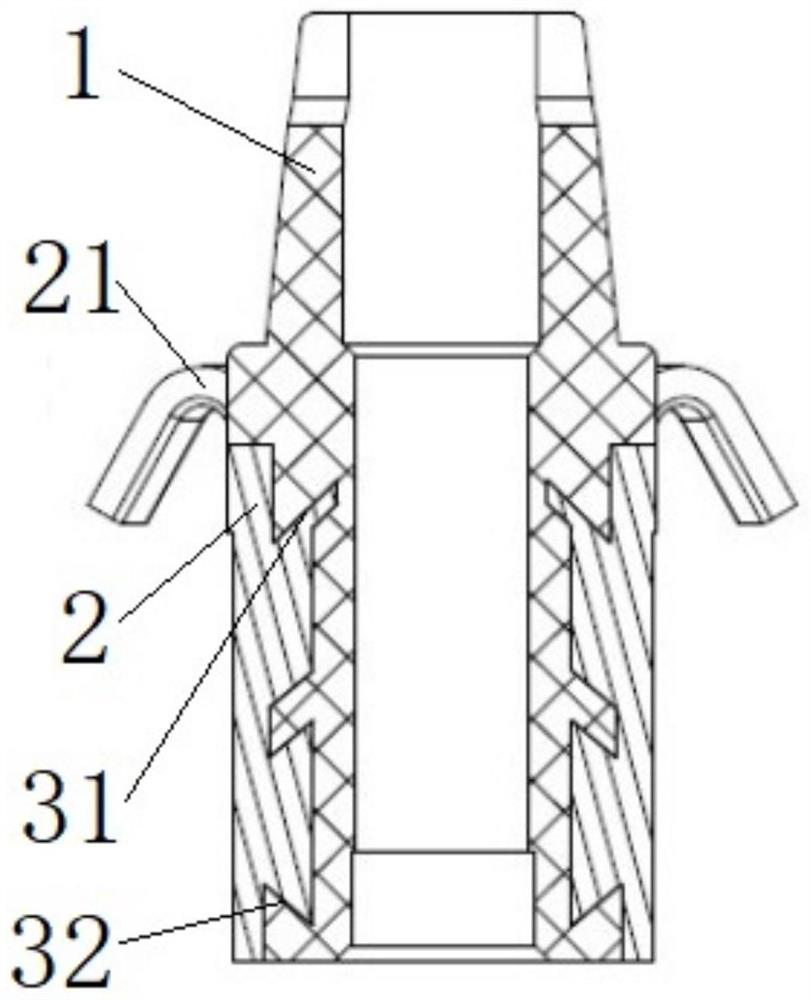
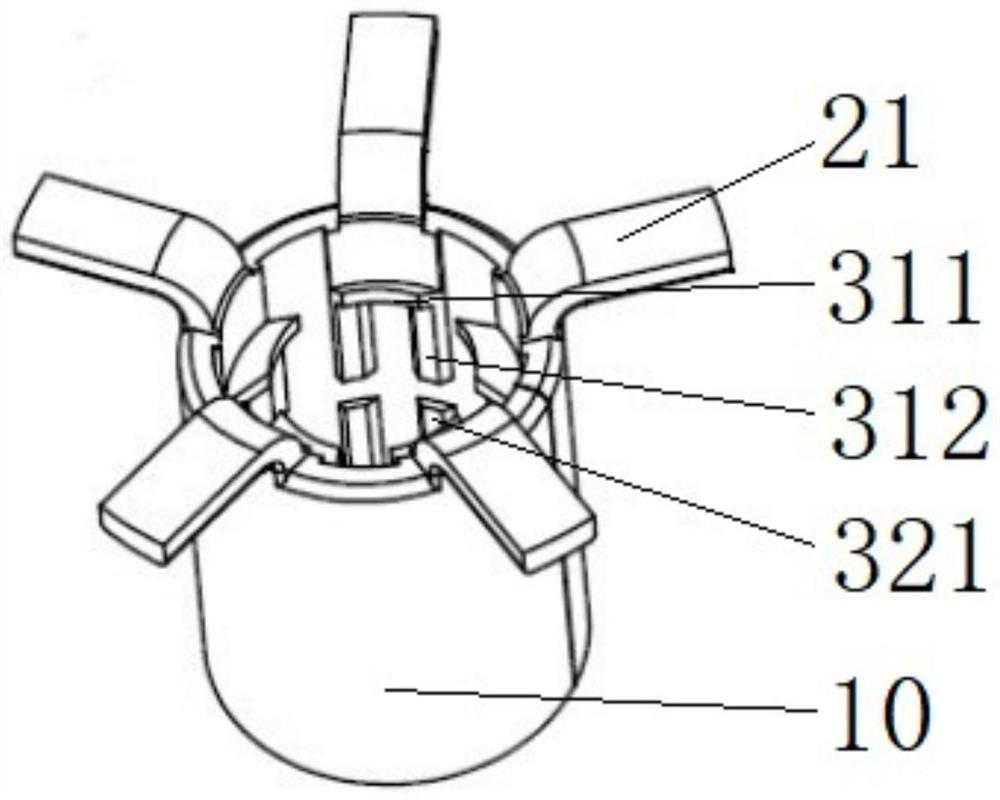
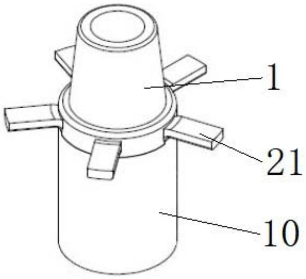
[0041] This embodiment provides as Figure 1 to Figure 4 A commutator shown includes an insulating base 1 and a commutator segment 2 . The commutator segment 2 is arranged on the periphery of the insulating base 1, and the commutating segment 2 has a plurality of K-shaped inner hooks for connecting to the insulating base 1, and the diameter of the commutator is greater than or equal to 7.8 mm and less than 8.8 mm. Specifically, the commutator segment 2 is made of copper or other materials. It should be noted that the diameter of the commutator refers to the diameter of the outer wall surface of the enclosed commutator segment 2, where figure 1 The outer wall surface of the middle commutator piece 2 is gradually shrunk in the direction away from the wire hook 21 of the commutator piece 2. At this time, the diameter of the commutator means that the outer wall surface of the commutator piece 2 is close to the wire hook 21 diameter of the end.

[0042] Such as figure 1 with ...

Embodiment 2

[0047] This embodiment provides a motor, which includes the commutator of Embodiment 1. It should be noted that the commutator in Embodiment 1 is suitable for motors with low noise, long life and high safety requirements.

Embodiment 3

[0049] This embodiment provides as Figure 5 with Image 6 A cutter is shown, which includes a cutter bar 4 , a plurality of first coulter teeth 52 , a plurality of second coulter teeth 62 , a guide head 71 , a first coulter 51 , a second coulter 61 and a cutter bar sleeve 8 . Such as Figure 5 with Image 6 As shown, some first coulter teeth 52 are arranged on the knife bar 4 along the circumferential direction; several second coulter teeth 62 are arranged on the knife bar 4 along the circumferential direction, and the first coulter teeth 52 are arranged on the second coulter teeth 62 is close to the head side of the knife bar 4, and the inner hook of the commutator is processed by the first coulter tooth 52 and the second coulter tooth 62.

[0050] By machining the commutator in Embodiment 1, the sum of the numbers of the first coulter teeth 52 and the second coulter teeth 62 is equal to the number of gaps between the K-shaped inner hooks. That is, during processing, the...


PUM


Abstract

The invention discloses a commutator, a motor and a cutter. The commutator comprises: an insulating substrate; the commutator comprises an insulating substrate, commutator segments, the commutator segments are arranged on the periphery of the insulating substrate, the commutator segments are provided with a plurality of K-shaped inner hooks so as to be connected to the insulating substrate, and the diameter of the commutator is greater than or equal to 7.8 mm and less than 8.8 mm. According to the commutator with the structure, the situation that a plurality of coulter teeth are arranged along the circumferential direction of the same height in the prior art is avoided by changing the arrangement of the cutter, so that the situation that the distance between adjacent coulter teeth is limited by the size of the commutator and the coulter teeth are too small is avoided; the service life of a cutter can be prolonged, the economic cost is reduced, and mass production can be achieved, so that the commutator with the diameter smaller than 8.8 mm and the K-shaped inner hook can be machined in a mass production mode.

Description

technical field [0001] The invention relates to the technical field of commutators, in particular to a commutator, a motor and a tool. Background technique [0002] As one of the core components of DC motors and AC motors, the commutator is a rotary electrical switch, a device connected to the winding coil of the motor, which periodically changes the distance between the motor rotor and the external circuit depending on the sliding contact of the motor carbon brush. The direction of the current between them makes the motor run continuously. The commutator includes a commutator piece, and the inner hook of the commutator piece has a C-type inner hook and a K-type inner hook. The processing technology of the C-type inner hook is more mature, and the K-type inner hook is more mature than the C-type inner hook. In other words, the bonding area between the K-type inner hook and the insulating substrate is larger, the bonding force is greater, and the comprehensive mechanical pro...

Claims


Application Information

Patent Timeline
Patent Type & Authority Applications(China)
IPC IPC(8): H01R39/04H01R43/06H02K13/00B23B27/00
CPCH01R39/04H01R43/06H02K13/006B23B27/00
Inventor 胡勇陈雷黄奇鹏
Owner SHENZHEN KAIZHONG PRECISION TECH CO LTD
Why Eureka
Try Eureka