Polishing equipment for flywheel shell machining

A flywheel shell and equipment technology, which is applied in metal processing equipment, grinding/polishing equipment, grinding machines, etc., can solve the problems of inability to grind the flywheel shell, increase processing costs, and discard the flywheel shell, so as to save grinding time and improve grinding efficiency , to ensure the effect of efficiency

Inactive Publication Date: 2022-03-15
潍坊鸿洋机械科技有限公司
View PDF0 Cites 0 Cited by
  • Summary
  • Abstract
  • Description
  • Claims
  • Application Information

AI Technical Summary

Problems solved by technology

[0007] The object of the present invention is to provide a kind of grinding equipment for flywheel shell processing to solve the problem of the traditional flywheel shell proposed in the above background technology. In order to facilitate the installation of the flywheel and ensure the connection and installation of the flywheel shell are firm, its structure is often not regular. There will also be a large number of grooves and protrusions on the surface, so the conventional grinding equipment cannot grind the flywheel shell, that is, the grinding of the flywheel shell needs manual work, which leads to the low efficiency of the grinding of the flywheel shell, and manual grinding It is often not possible to ensure the uniformity of the grinding force well, so that the flatness of the grinding surface is not high, and the service life of the flywheel housing is not greatly improved, and manual grinding is prone to over-grinding, resulting in damage to the cast flywheel housing, resulting in increased processing costs. When the flywheel housing is being ground, the grinding structure will rub against the flywheel housing during the grinding process, causing the flywheel housing to shift during the grinding process, resulting in flaws in the grinding process. At this time, it is necessary to fix the flywheel housing, and manpower cannot do it well. Fixing the flywheel housing will cause the flywheel housing to shake. Generally, a clamping device is used to clamp the flywheel housing, and then it is manually polished. The clamping device generally combines the two splints in the middle through a screw rod, so that the flywheel housing is in the middle. It is fixed under pressure, but the size of the clamping force is determined by the number of turns obtained by manually turning the screw rod, which makes it easy to cause deformation of the flywheel housing due to excessive clamping force, resulting in the scrapping of the flywheel housing, resulting in increased costs. The current grinding is clamped and polished by a clamping device. After one side is polished, the clamping structure needs to be released, and then the flywheel housing is turned over, and the flywheel housing is clamped here, so as to carry out the opposite side. Grinding makes the grinding process cumbersome, resulting in low grinding efficiency, making the processing speed of the flywheel shell slow, and increasing the probability of clamping deformation of the flywheel shell

Method used


Image

  • Polishing equipment for flywheel shell machining
  • Polishing equipment for flywheel shell machining
  • Polishing equipment for flywheel shell machining

Examples


Embodiment Construction

[0030] The following will clearly and completely describe the technical solutions in the embodiments of the present invention with reference to the accompanying drawings in the embodiments of the present invention. Obviously, the described embodiments are only some, not all, embodiments of the present invention. Based on the embodiments of the present invention, all other embodiments obtained by persons of ordinary skill in the art without making creative efforts belong to the protection scope of the present invention.

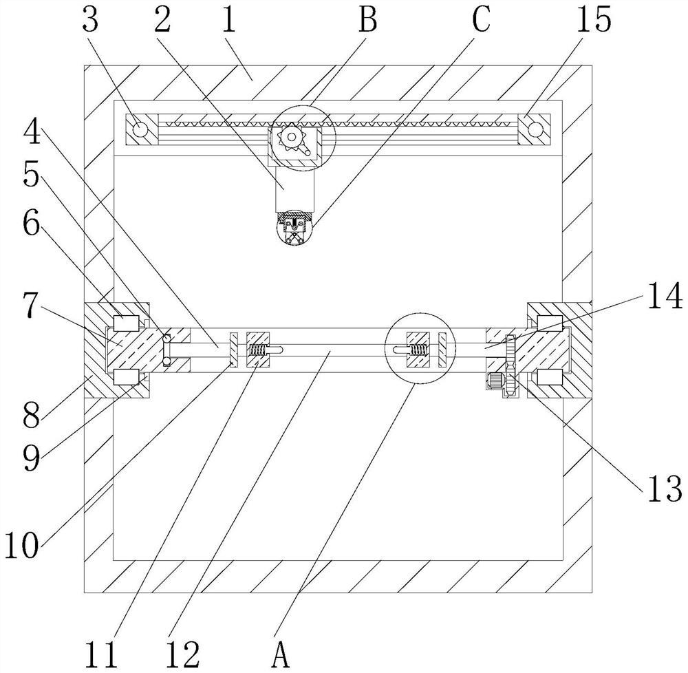
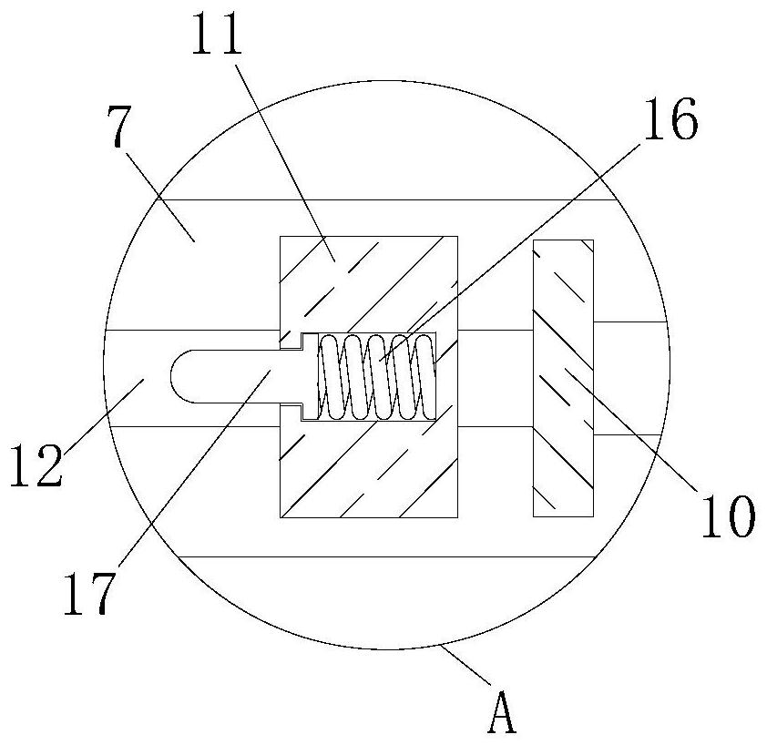
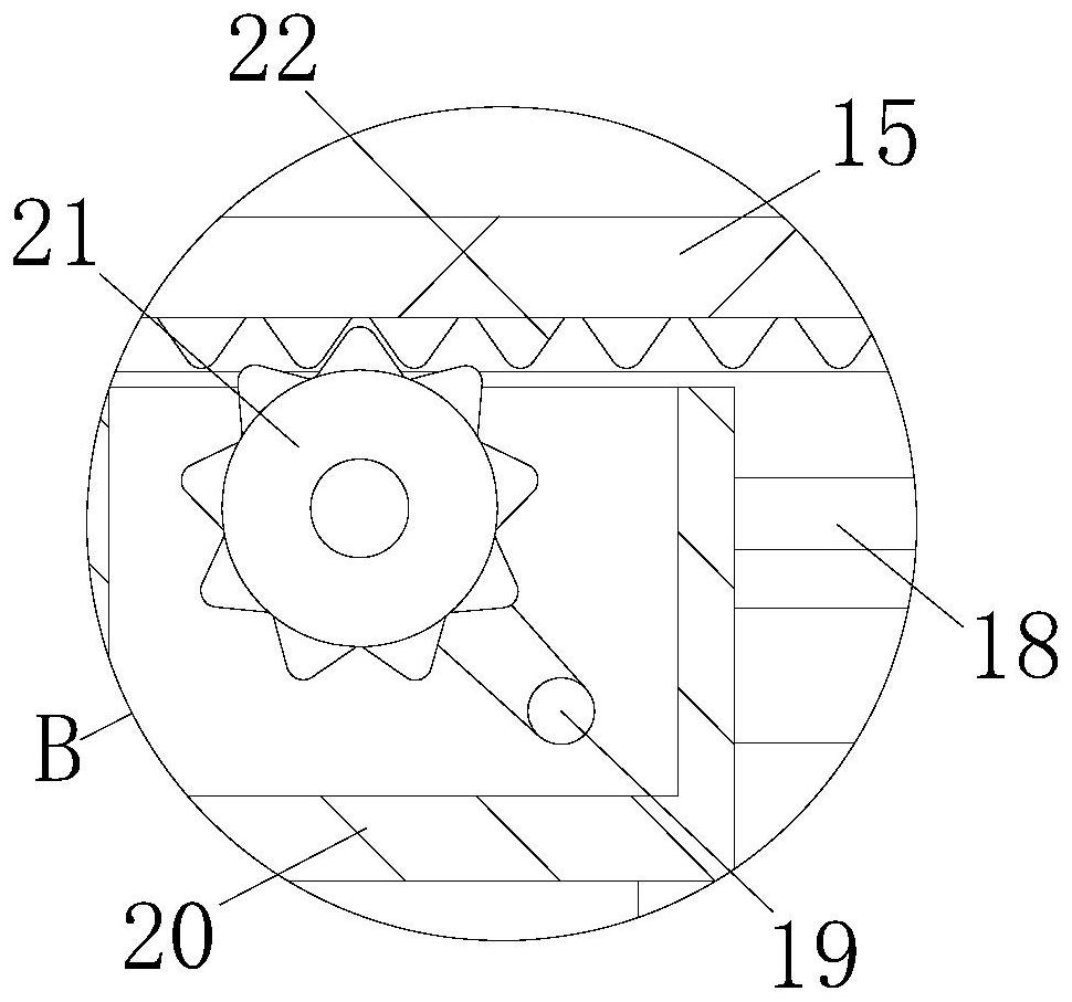
[0031] see figure 1 , Figure 4 , Figure 5 , Figure 7 , Figure 8 and Figure 9, the present invention provides a technical solution: a kind of grinding equipment for flywheel shell processing, including a shell 1, in order to ensure stable clamping and realize the flipping of the flywheel shell, a slide rail 8 is connected to the inside of the shell 1, and the slide rail One side of the 8 is connected with a moving plate 7, the inside of the moving pla...


PUM


Abstract

The grinding equipment for flywheel shell machining comprises a shell, a sliding rail is arranged and connected in the shell, a movable plate is connected to one side of the sliding rail, a fixed plate is arranged in the movable plate, a clamping plate is arranged on one side of the fixed plate, a clamping rod is connected to one side of the clamping plate, and a clamping lead screw is connected to the interior of the clamping plate. A movable lead screw is arranged in the shell, a movable rod is connected to the periphery of the movable lead screw, a movable rail is arranged in the movable rod, and a movable block is connected into the movable rail. According to the grinding equipment for flywheel shell machining, the arranged pressing wheel structure is utilized, grinding is conducted through the grinding strips, so that the distance between the pressing wheels is changed through stretching and retracting of the telescopic rods, the grinding area is changed, grinding of the whole flywheel shell is achieved, grinding can be conducted on the surface structure of the flywheel shell, automatic grinding is achieved, manpower is not needed, and the grinding efficiency is improved. And the grinding efficiency is further ensured.

Description

technical field [0001] The invention relates to the technical field of flywheel housing processing, in particular to a grinding device for flywheel housing processing. Background technique [0002] The flywheel housing is a part of the power assembly of the automobile. It carries the mass of the transmission and acts as a fulcrum for power transmission. It is one of the important components for the normal driving of the vehicle. It is generally formed by integral casting, and then due to the limitation of casting technology, There are often many pits and a large number of burrs on the surface. These flaws will affect the rotation of the flywheel in the flywheel housing, resulting in damage to the flywheel or wear and deformation of the flywheel, which will cause problems in the power transmission of the car. Therefore, the casting of the flywheel housing is completed Finally, it is necessary to use grinding equipment for subsequent processing to polish the concave and convex...

Claims


Application Information

Patent Timeline
IPC IPC(8): B24B9/04B24B41/06B24B47/22B24B41/02B24B41/04B24B55/00
CPCB24B9/04B24B41/06B24B47/22B24B41/02B24B41/04B24B55/00
Inventor 于鲁伟孙志鹏
Owner 潍坊鸿洋机械科技有限公司
Why Eureka
Try Eureka