Heat storage element for large-flow high-temperature high-pressure high-speed gas environment

A high-temperature, high-pressure, high-velocity gas technology, which is applied in the direction of measuring devices, aerodynamic tests, and machine/structural component testing, can solve problems that affect the safety of wind tunnel operation, affect the accuracy of test data, and reduce the reliability of heating elements. , to achieve the effect of improving reliability and wind tunnel test efficiency, ensuring the cleanliness of the test airflow, and reducing the risk of local overheating

Active Publication Date: 2022-03-18
中国空气动力研究与发展中心超高速空气动力研究所
View PDF15 Cites 2 Cited by
  • Summary
  • Abstract
  • Description
  • Claims
  • Application Information

AI Technical Summary

Problems solved by technology

[0006] The pebble bed heat storage element has the following disadvantages: a. The contact area between the heat storage ball and the electric heating element is small, and the heat transfer efficiency is low, resulting in a low heating rate of the heat storage ball, long preheating time, and the electric heating element Local over-temperature damage affects the reliability of the heating element and the efficiency of the wind tunnel test; b. The heat storage balls are naturally stacked in the container. Under the long-term repeated thermal expansion and contraction conditions, the small balls will move and squeeze irregularly. And generate a large stress, resulting in deformation or even damage to the lining cylinder and the electric heating element, reducing the reliability of the electric heating element; c. The heat storage ball is a ceramic ball, which is easy to drop slag. The slag is more serious, will pollute the test airflow, have a sandblasting effect on the test model, and affect the accuracy of the test data; d. The hot balls are easy to float up under the action of buoyancy, which may damage the electrical connection and downstream equipment in the upper head, and affect the safety of the wind tunnel operation; , It is inconvenient to disassemble, and it cannot fix the heating element, which will cause the heating element to shift and tilt, and affect the reliability of the heating element and the efficiency of the wind tunnel test

Method used


Image

  • Heat storage element for large-flow high-temperature high-pressure high-speed gas environment
  • Heat storage element for large-flow high-temperature high-pressure high-speed gas environment
  • Heat storage element for large-flow high-temperature high-pressure high-speed gas environment

Examples


Embodiment 1

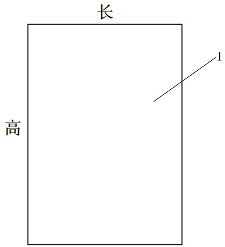
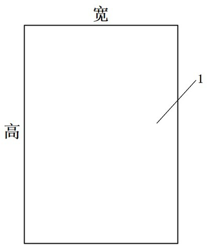
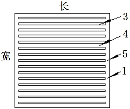
[0042] Such as Figure 1a , Figure 1b , Figure 1c , figure 2 As shown, the basic shape body 1 of the present embodiment is a cuboid with a length of 100 mm * a width of 100 mm * a height of 150 mm; times, the gap ratio is 0.33; the depth of the gap 3 of the grid is 150 mm, and the thickness of the outer wall 5 is 5 mm.

[0043] The basic shape 1 of this embodiment is processed by precision casting, and the 3mm gap can be cast directly, or it can be casted with a 12mm gap first, and then inserted and welded with a 6mm grating.

[0044] The basic body 1 and matching block 2 of this embodiment are used for image 3 , Figure 4 The regenerative heater shown is composed of an electric heating element, a regenerative element, a heat insulation layer, and a heater shell.

[0045] The arrangement of the basic body 1 and the matching block 2 in this embodiment is shown in Figure 5 .


PUM

PropertyMeasurementUnit
Flatnessaaaaaaaaaa
Roughnessaaaaaaaaaa
Thicknessaaaaaaaaaa

Abstract

The invention belongs to the technical field of hypersonic wind tunnel test equipment, and discloses a heat storage element for a large-flow high-temperature high-pressure high-speed gas environment. The heat storage element is a metal element which is stacked in the heat storage type heater in a layered mode and used for storing heat and comprises a basic body and a matching block body, the basic body is square grid bodies which are filled in a central cavity of a lining cylinder of the heat storage type heater in a layered mode, and each layer of square grid bodies are arranged in an array mode. The matching block body is a matching grid body which corresponds to the basic body and is suitable for being filled at the edge of a lining cylinder of the heat accumulating type heater; gaps facing incoming flow and penetrating up and down are formed in the basic body and the matching block body, and the gap ratio of the heat storage element is 0.33; the weight of each basic body and each matching block body is greater than or equal to the buoyancy borne by each basic body and each matching block body in a flow field. The heat storage element does not move, does not drop slag, does not float upwards, is convenient to dismount, mount and fix, guarantees the reliability of the heat storage type heater, and improves the cleanliness of test airflow and the quality and efficiency of a wind tunnel test.

Description

technical field [0001] The invention belongs to the field of hypersonic wind tunnel test equipment, and in particular relates to a heat storage element used in a high-flow, high-temperature, high-pressure, and high-speed gas environment. Background technique [0002] In a conventional hypersonic wind tunnel using air as the test medium, due to the extremely high gas flow velocity, reaching Mach number 5 to Mach number 10, the violent expansion of the gas flow through the nozzle will cause water vapor and carbon dioxide to condense, resulting in irregularities in the flow field. The uniformity makes the test data inaccurate, which is not allowed in the hypersonic wind tunnel aerodynamic test. Therefore, in a conventional hypersonic wind tunnel with a large flow of high-speed air as the medium, it is necessary to install a regenerative heater to heat the airflow to the required anti-condensation temperature. Since the main purpose of the hypersonic wind tunnel is to carry out...

Claims


Application Information

Patent Timeline
IPC IPC(8): G01M9/04
CPCG01M9/04
Inventor 陈久芬徐洋章起华朱涛蒋万秋范孝华孙启志茆青母波
Owner 中国空气动力研究与发展中心超高速空气动力研究所
Why Eureka
Try Eureka