Optical imaging system, flight simulation compound system and flight simulation method

An optical imaging system and optical imaging technology, applied in the simulation devices, optics, simulators and other directions of space navigation conditions, can solve the problems of expensive molding optical materials, lack of multi-channel transmission function, poor stereo vision, etc., to prevent optical Imaging light diffraction, improving simulated visual effects, avoiding dark field effects

Active Publication Date: 2022-03-18
BEIJING WINCOMN TECH DEV
View PDF16 Cites 0 Cited by
  • Summary
  • Abstract
  • Description
  • Claims
  • Application Information

AI Technical Summary

Problems solved by technology

[0003] The inventors have discovered that the spherical screen and the circular flight simulation system have the problems of large volume of the optical system, dark field fusion zone in the optical imaging system, easy deformation of the optical imaging equipment and expensive molding optical materials due to the problems of the optical imaging system, and the viewpoint is on the spherical surface. The center cannot be adjusted. In actual use, the parallax can be eliminated by using expensive optical equipment or processing, and it can only be viewed outside the center of the ball, and the viewer will block the picture, which makes it difficult to further improve the simulation effect; while the three-splicing splicing screen The flight simulation system is a common solution in the market. Its stereoscopic vision is poor, and it does not have the function of multi-channel transmission. It cannot be compatible with a large amount of information processing, and the overall visual effect is poor due to the large gap between different layers of the optical imaging system; VR technology It is a technology that has emerged in recent years and is limited to single-person viewing. Due to the inherent defects of 3D optical viewing angles, long-term use is easy to cause dizziness and cannot be used for long-term flight simulation.

Method used


Image

  • Optical imaging system, flight simulation compound system and flight simulation method
  • Optical imaging system, flight simulation compound system and flight simulation method
  • Optical imaging system, flight simulation compound system and flight simulation method

Examples


Embodiment Construction

[0048] The subject matter of the invention will now be discussed with reference to several exemplary embodiments. It should be understood that these embodiments are discussed only to enable those of ordinary skill in the art to better understand and thus implement the content of the present invention, and do not imply any limitation to the scope of the present invention.

[0049] As used herein, the term "comprising" and variations thereof are to be read as open-ended terms meaning "including but not limited to". The term "based on" is to be read as "based at least in part on". The terms "one embodiment" and "an embodiment" are to be read as "at least one embodiment". The term "another embodiment" is to be read as "at least one other embodiment".

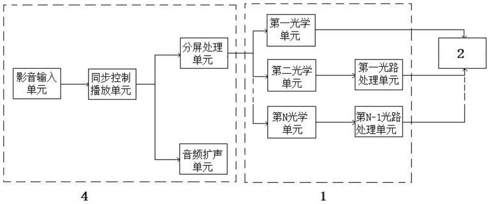
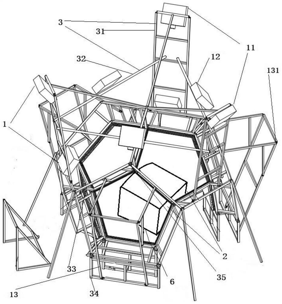
[0050] This embodiment discloses an optical imaging system, as follows figure 1 The shown includes a light source module 1, an optical imaging module 2, a support module 3 and a control module 4; the optical imaging module 2 is f...


PUM


Abstract

The invention relates to the technical field of optical imaging and simulation, in particular to an optical imaging system, a flight simulation compound system and a flight simulation method, and the flight simulation compound system comprises a spliced optical imaging system and a simulation cabin system; the optical imaging system comprises a light source module, an optical imaging module, a supporting module and a control module. The problems that an existing optical system has a dark field fusion zone, the size of the optical system is large, and interlayer abutted seams are large are solved. A transition area is arranged at the edge of an image when the split-screen processing unit is adopted to carry out split-screen processing on an image signal, and the edge is blackened, so that a dark field effect can be prevented; the problem that the viewpoint cannot be adjusted in the sphere center is solved; the sizes of the bracket and the system are reduced; interlayer abutted seams of the optical imaging module are greatly reduced, and the continuity of the simulated visual effect is further improved.

Description

technical field [0001] The invention relates to the technical field of optical imaging and simulation, in particular to an optical imaging system, a flight simulation composite system and a flight simulation method. Background technique [0002] With the development of flight simulation technology, the performance of flight simulators has been continuously improved, and the use of flight simulators for flight training has gradually become an important means of civil aviation and national defense and an important content of weaponry development. A large number of flight simulators in the market use spherical, circular or triple-shaped visual display forms and VR helmets. These simulators currently have various problems. [0003] The inventors have discovered that the spherical screen and the circular flight simulation system have the problems of large volume of the optical system, dark field fusion zone in the optical imaging system, easy deformation of the optical imaging eq...

Claims


Application Information

Patent Timeline
Patent Type & Authority Applications(China)
IPC IPC(8): G09B9/30G02B27/01
CPCG09B9/30G02B27/0101G02B27/0149
Inventor 郭昊韩松涛江瑶刘昌喜沈湘慧刘勇
Owner BEIJING WINCOMN TECH DEV
Why Eureka
Try Eureka