Method for electrocatalytic conversion of carbon dioxide by microorganisms

A technology of catalytic conversion and microbial electricity, which is applied in the direction of electrodes, electrolysis process, electrolysis components, etc., can solve the problems of low efficiency of biological methods, and achieve the effect of alleviating the problem of CO2 resource utilization, improving efficiency and high current response

Active Publication Date: 2022-03-22
ZHEJIANG UNIV OF TECH
View PDF8 Cites 2 Cited by
  • Summary
  • Abstract
  • Description
  • Claims
  • Application Information

AI Technical Summary

Problems solved by technology

However, the traditional biological method is inefficient, and it is urgent to develop a method that can rapidly convert CO 2 environmentally friendly technology

Method used


Image

  • Method for electrocatalytic conversion of carbon dioxide by microorganisms
  • Method for electrocatalytic conversion of carbon dioxide by microorganisms
  • Method for electrocatalytic conversion of carbon dioxide by microorganisms

Examples


Embodiment 1

[0028] Embodiment 1: microbial electrolysis cell start-up stage

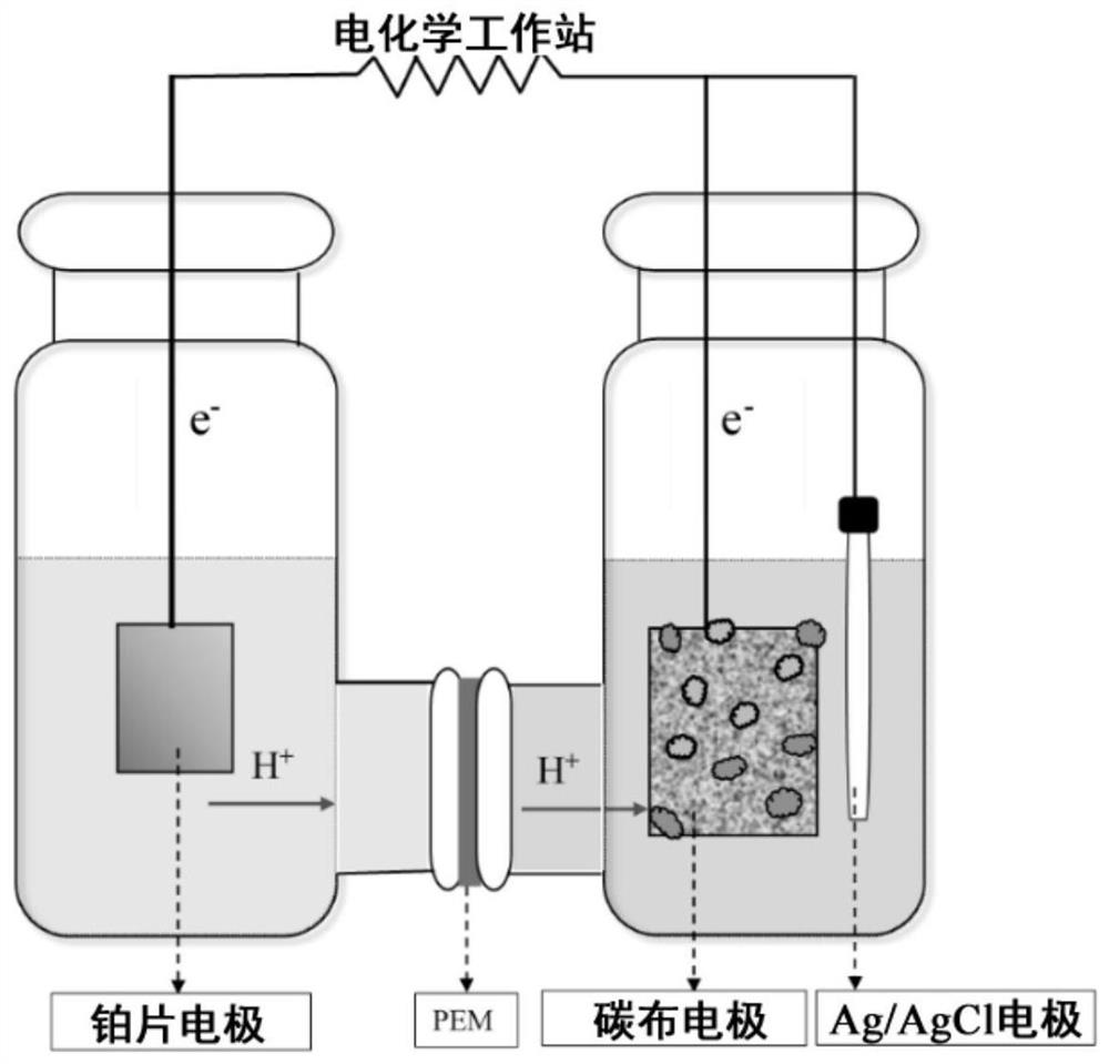
[0029] refer to figure 1 , the microbial electrolytic cell is made up of cathode chamber, anode chamber, and described cathode chamber and anode chamber are communicated by proton exchange membrane, and described proton exchange membrane refers to Nafion 117 proton exchange membrane; In described cathode chamber, carbon cloth electrode is used as cathode, The Ag / AgCl electrode is the reference electrode; the platinum sheet electrode in the anode chamber is the anode, and the distance between the cathode and the anode is 5 cm. The top of the cathode chamber is provided with an aeration port and a sampling port, the aeration port is connected with a 0.45 μm filter membrane for the filtration of microorganisms and particles, and the sampling port is used for the collection and analysis of the catholyte; the carbon cloth electrode, Ag / AgCl The electrode and the platinum sheet electrode are respectively connected wi...

Embodiment 2

[0034] Example 2: Catalytic conversion of CO by microbial electrolysis cells at different cathode potentials 2 ability

[0035] 1. Changes in current at different potentials

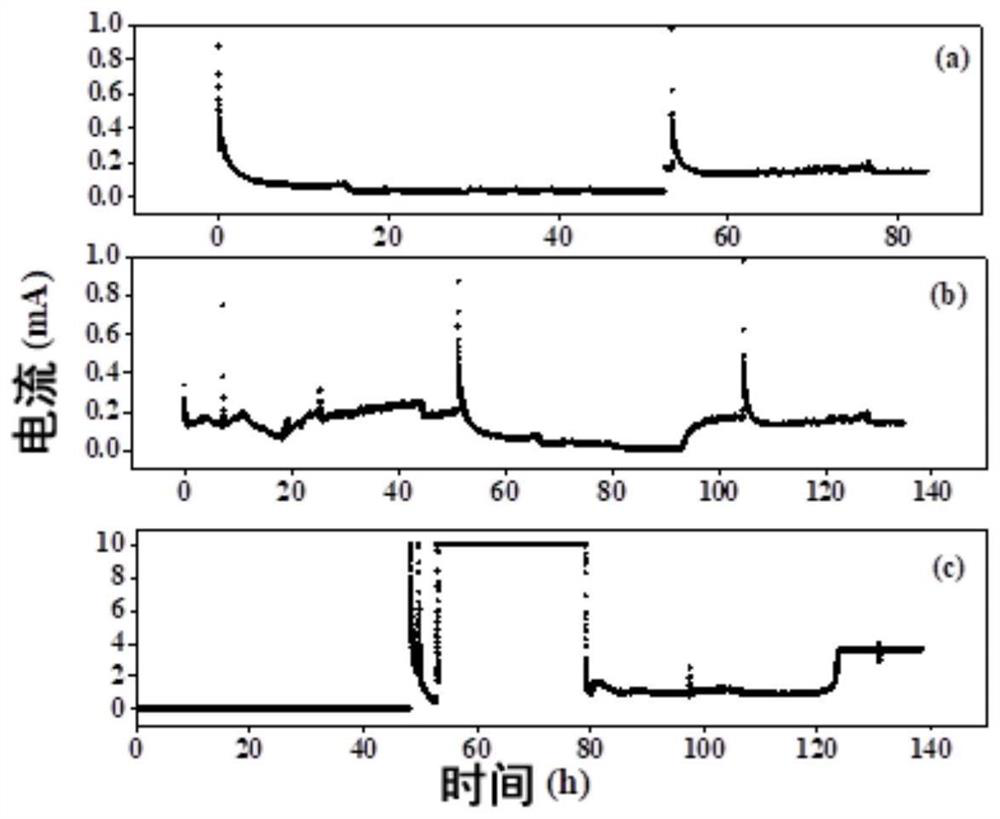
[0036] After embodiment 1 microbial electrolytic cell starts successfully, catholyte chamber is replaced with new catholyte, and anode chamber is replaced with new anolyte, and it is -0.6V to run 140h under the condition of cathodic potential, and each experiment period (5 days / period) ends Afterwards, both the catholyte and the anolyte were replaced, and with 40mL min -1 into CO at a rate of 2 Gas for 15min to make the CO in the catholyte 2 The concentration reaches saturation, and the current change during operation is referred to figure 2 Middle (b). After the microbial electrolytic cell started running, 4mL was sampled from the cathode chamber every 10 hours, and the same volume of catholyte (same as in Example 1) was added, and the Shimadzu Total Organic Carbon Analyzer was used to detect inor...

Embodiment 3

[0040] Example 3: Biofilm Electrochemical Activity at Different Cathode Potentials

[0041] Example 2 After the current of the microbial electrolytic cell reaches stability, the electrochemical workstation is used for cyclic voltammetry scanning analysis. The potential range of the scanning is -1.0~1.0V, and the rate is 1mV s -1 .

[0042] Under the same conditions, the catholyte without activated sludge and sodium 2-bromoethanesulfonate is used as a contrast, i.e. blank carbon cloth, and other operations are the same as in Example 1.

[0043] Such as Figure 5 As shown, when the blank carbon cloth was used as the cathode, no redox peak was detected, which indicated the lack of participation of electron mediators in the process. Compared with the control group, the response of the cathodic current in the cyclic voltammetry curve of the experimental group is higher than that of the control group in the scanning range, and the current range is about -0.04~0.08A (-0.6V), -0.017~0...


PUM

PropertyMeasurementUnit
thicknessaaaaaaaaaa
ion source temperatureaaaaaaaaaa

Abstract

The invention discloses a method for electrocatalytically converting carbon dioxide by microorganisms, which comprises the following steps of: performing conversion by adopting a microbial electrolytic tank, taking a carbon cloth electrode as a cathode, taking Ag / AgCl as a reference electrode and taking a platinum sheet electrode as an anode; activated sludge and cathode liquor are added into a cathode chamber, and operation is conducted for 140 h at the temperature of 30 DEG C and the cathode potential of-0.6 V to-0.8 V. According to the invention, the cathode chamber is inoculated with the activated sludge with efficient CO2 conversion capability, so that the efficiency of catalytic conversion of CO2 is effectively improved. And through regulation and control of the cathode potential, the system performance is further improved. In the process of catalytic conversion of CO2, a high value-added product is synthesized, and the problem of CO2 recycling is relieved.

Description

(1) Technical field [0001] The invention relates to the field of microbial electrochemistry, in particular to a microbial electrocatalytic conversion of CO 2 Methods. (2) Background technology [0002] Climate change is the biggest environmental challenge in the world, and greenhouse gas emissions are the main cause of global warming since the middle of the 20th century. carbon dioxide (CO 2 ) as the most important greenhouse gas, its emissions accounted for 68% of the total man-made greenhouse gas emissions. According to the forecast of the International Energy Agency (IEA), by 2030 CO 2 Emissions will be 63% higher than in 2004. In recent years, regarding CO 2 Initiatives to reduce emissions have spread around the world. As a responsible major country, my country has proposed the goal of peaking carbon dioxide emissions by 2030 and achieving carbon neutrality by 2060. for CO 2 Emission reduction and the development of efficient and economical deepening treatment tec...

Claims


Application Information

Patent Timeline
Patent Type & Authority Applications(China)
IPC IPC(8): C25B3/07C25B3/26C12P7/18C12P7/44C25B11/085
CPCC25B3/07C25B3/26C12P7/18C12P7/44C25B11/085
Inventor 张士汉应赞赟叶杰旭高家玲
Owner ZHEJIANG UNIV OF TECH
Why Eureka
Try Eureka