Mould grouting device for automatic lining trolley
A technology for lining trolleys and grouting devices, which is applied in shaft lining, tunnel lining, shaft equipment, etc., can solve problems such as low work efficiency, large space occupation, and high labor intensity, and achieve improved pouring efficiency, faster flow rate, and reduced The effect of pouring difficulty
- Summary
- Abstract
- Description
- Claims
- Application Information
AI Technical Summary
Problems solved by technology
Method used
Image
Examples
Embodiment 1
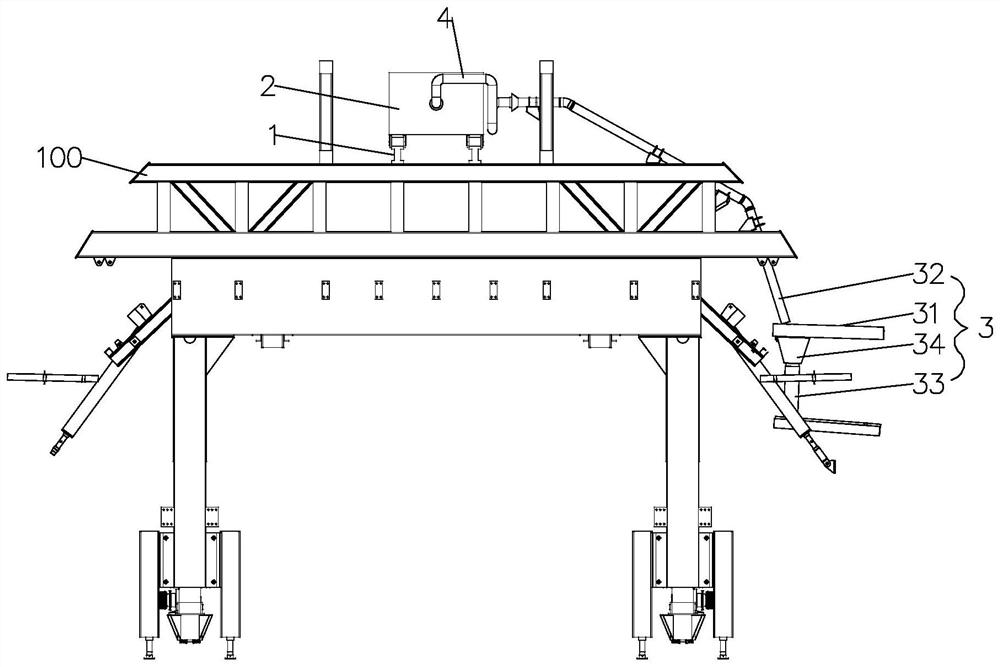
[0040] refer to figure 1 , the device includes a transportation track 1, a transportation pump truck 2, a grouting pipeline 3 and a transfer elbow 4. Wherein, the transportation track 1 and the transportation pump truck 2 are all arranged on the trolley frame 100, specifically, the trolley frame 100 is arranged along the traveling direction of the trolley, and is used as the main supporting structure of the trolley to support the two sides of the trolley. Side and top molds.
[0041] The transport track 1 is arranged in the top space of the trolley frame 100, and is also arranged along the traveling direction of the trolley. The transport track 1 includes two monorails arranged in parallel, which can be welded and fixed on the trolley frame 100, or can be passed through Bolts are fixed on the trolley stand 100. In this embodiment, the transport track 1 uses I-beam as the material, and brake structures are arranged at both ends.
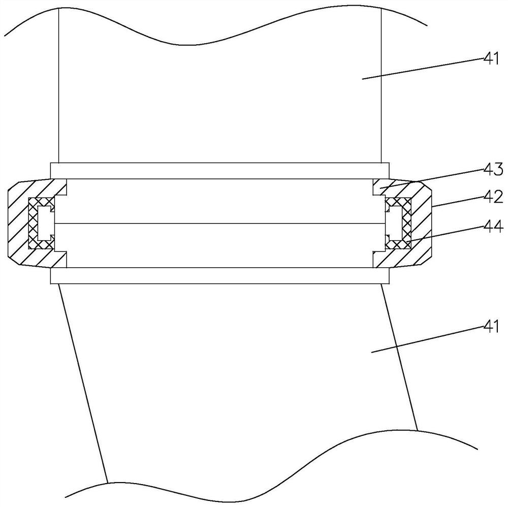
[0042] refer to figure 1 and 2, the transpo...
Embodiment 2
[0049] refer to Figure 4 , as another embodiment of the present application, the grouting device adds a pressurized assembly 5 on the basis of Example 1, and the pressurized assembly 5 is arranged between the transfer elbow 4 and the upper pipeline 32, and the pressurized The component 5 exerts pressure on the mortar entering the upper 32 pipeline to speed up the flow velocity of the mortar and improve the pouring efficiency of the lining structure.
[0050] The pressurizing assembly 5 includes a two-part structure of a storage box 51 and a pressurizing part, wherein the storage box 51 is arranged on both sides of the transportation track 1 along the direction of the transportation track 1, and is located between the transportation pump truck 2 and the upper pipeline 32 room, the inside of the material storage box 51 is divided into several single rooms, and each single room is connected with at least one group of grouting pipelines 3, and each single room is connected with a...
PUM
 Abstract
Description
Claims
Application Information
 - R&D
- Intellectual Property
- Life Sciences
- Materials
- Tech Scout
- Unparalleled Data Quality
- Higher Quality Content
- 60% Fewer Hallucinations
Browse by: Latest US Patents, China's latest patents, Technical Efficacy Thesaurus, Application Domain, Technology Topic, Popular Technical Reports.
© 2025 PatSnap. All rights reserved.Legal|Privacy policy|Modern Slavery Act Transparency Statement|Sitemap|About US| Contact US: help@patsnap.com


