Water combustion-supporting device for combustion engine

A technology of a burner and a water tank, which is applied in the combustion method, combustion equipment, steam generation method using pressure combustion, etc., can solve the problems of poor energy saving and environmental protection effect, pollution of the environment by tail smoke, increase in cost, etc., so as to shorten and improve the combustion distance. Flame temperature and fire intensity, the effect of increasing the burning rate

Pending Publication Date: 2022-03-22
吉林市金海热力设备制造有限公司
View PDF0 Cites 0 Cited by
  • Summary
  • Abstract
  • Description
  • Claims
  • Application Information

AI Technical Summary

Problems solved by technology

[0002] The function of the burner is to mix fuel oil or gas with air and spray it continuously from the nozzle for combustion, so as to obtain the required heat energy. Because the burner has the advantages of energy saving and environmental protection and the characteristics of continuous and stable work, it has been used in industrial or civil It is widely used in boilers and kilns; since the burner adopts jet combustion, in order to improve the combustion efficiency of fuel, it is not only necessary to send in a sufficient amount of air for combustion support, but also to have a certain depth in the furnace so that the injected fuel can burn as much as possible. Due to the limited proportion of oxygen in the air, part of the unburned fuel will still be discharged to the flue for combustion with the high-speed flue gas, which not only causes fuel waste, but also produces black tail smoke to pollute the environment. The tail smoke treatment device is used for purification, and the waste water or residue generated by the tail smoke treatment device needs to be treated twice, which further increases the cost, and the effect of energy saving and environmental protection is poor. How to make fuel combustion fully improve the purity of tail smoke to achieve energy saving and environmental protection And how to improve the thermal efficiency and adaptability of the burner is a technical problem that those skilled in the art always want to solve

Method used


Image

  • Water combustion-supporting device for combustion engine
  • Water combustion-supporting device for combustion engine
  • Water combustion-supporting device for combustion engine

Examples


Embodiment Construction

[0031]The technical solutions in the embodiments of the present application will be further shown below in conjunction with the accompanying drawings, so as to describe the technical solutions in the embodiments of the present application in more detail. Those of ordinary skill in the art should know that the embodiments described in the present application are only Some, but not all, embodiments of the device of the present application. Based on the embodiments disclosed in this application, all other embodiments obtained by persons of ordinary skill in the art without making creative efforts fall within the scope of protection of this application.

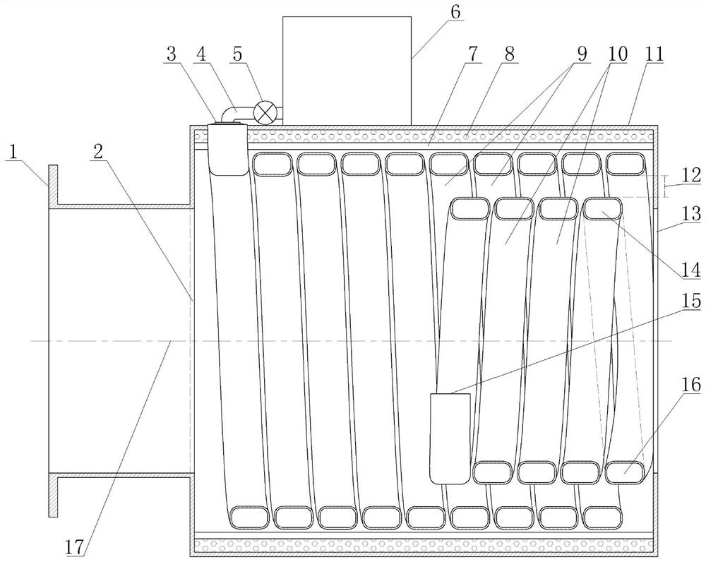
[0032] Burner water combustion device, such as figure 1 As shown, it has a water tank 6 and a fire tube 11. The front end of the fire tube is provided with a fire inlet 2, and the rear end of the fire tube is provided with a fire hole 13. The fire tube is provided with a steam generation pipeline 9 and a steam dry distillation pi...


PUM


Abstract

A water combustion-supporting device for a combustion engine belongs to a matching device of the combustion engine and is provided with a water tank and a fire cylinder, a fire inlet hole is arranged at the front end of the fire cylinder, a fire spraying hole is arranged at the rear end of the fire cylinder, a steam generating pipeline and a steam dry distillation pipeline are arranged in the fire cylinder, and the steam generating pipeline is arranged on the periphery of the steam dry distillation pipeline. A fire passing gap is formed between the steam generation pipeline and the steam dry distillation pipeline; a front-end water inlet of the steam generation pipeline is communicated with the water tank, a rear-end air outlet of the steam generation pipeline is communicated with a rear-end air inlet of the steam dry distillation pipeline, and a front port of the steam dry distillation pipeline is provided with a combustion-supporting nozzle; the device can assist the combustion engine in combusting fuel more sufficiently, so that the cleanliness of tail smoke is improved, and the energy-saving and environment-friendly effects are good.

Description

technical field [0001] The invention relates to a matching device for a burner, in particular to a water-assisted combustion device for a burner. Background technique [0002] The function of the burner is to mix fuel oil or gas with air and spray it continuously from the nozzle for combustion, so as to obtain the required heat energy. Because the burner has the advantages of energy saving and environmental protection and the characteristics of continuous and stable work, it has been used in industrial or civil It is widely used in boilers and kilns; since the burner adopts jet combustion, in order to improve the combustion efficiency of fuel, it is not only necessary to send in a sufficient amount of air for combustion support, but also to have a certain depth in the furnace so that the injected fuel can burn as much as possible. Due to the limited proportion of oxygen in the air, part of the unburned fuel will still be discharged to the flue for combustion with the high-sp...

Claims


Application Information

Patent Timeline
Patent Type & Authority Applications(China)
IPC IPC(8): F22B1/22F22B37/12F22D5/34F22G3/00F23L7/00
CPCF22B1/22F22B37/12F22D5/34F22G3/002F23L7/007
Inventor 刘金山卢文纪延华
Owner 吉林市金海热力设备制造有限公司
Why Eureka
Try Eureka