Gear fatigue test piece and manufacturing method

A technology of fatigue test and manufacturing method, which is applied in the testing of mechanical components, testing of machine/structural components, measuring devices, etc., which can solve the problem of inability to consider the structural characteristics of gear teeth, surface processing and process conditions, complex test process, It takes a long time and other problems to achieve the effect of shortening the fatigue test time and simplifying the test process

Pending Publication Date: 2022-03-22
AECC HUNAN AVIATION POWERPLANT RES INST
View PDF0 Cites 0 Cited by
  • Summary
  • Abstract
  • Description
  • Claims
  • Application Information

AI Technical Summary

Problems solved by technology

The test process of the test piece requires the trial production of special fixtures so that the gear teeth can be evenly loaded, the test process is complicated, and the equipment involved in the test is mainly fatigue testing machine, vibration exciter, etc., and the cost is high
[0003] Among them, the first type of gear fatigue test piece cannot consider the gear tooth structure characteristics, surface processing and process conditions, so there is a certain difference between the gear tooth fatigue limit result obtained by using the gear fatigue test piece and the actual result; the second type of gear fatigue test piece Test piece, when using this kind of gear fatigue test piece to test, the gear tooth pulse load frequency is generally (100-300) Hz, and the long life (10) under one stress level is completed. 7 The fatigue test takes a long time, and special fixtures need to be trial-produced to ensure that the teeth are evenly loaded. In addition, it is difficult to load pulse loads on helical gears

Method used


Image

  • Gear fatigue test piece and manufacturing method
  • Gear fatigue test piece and manufacturing method
  • Gear fatigue test piece and manufacturing method

Examples


Embodiment Construction

[0038] In order to make the purpose, technical solutions and advantages of the embodiments of the present invention more clear, the technical solutions in the embodiments of the present invention will be clearly and completely described below in conjunction with the accompanying drawings in the embodiments of the present invention. Obviously, the described embodiments It is a part of embodiments of the present invention, but not all embodiments. Based on the embodiments of the present invention, all other embodiments obtained by persons of ordinary skill in the art without making creative efforts belong to the protection scope of the present invention.

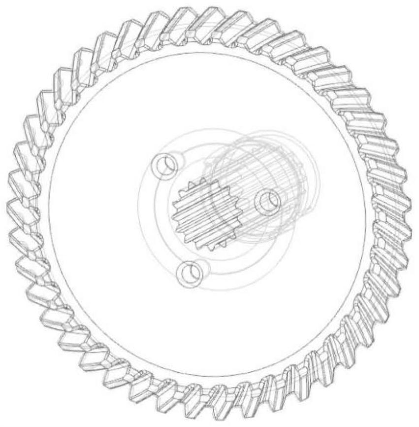
[0039] refer to figure 2 As shown, spiral bevel gears are widely used in mechanical transmission fields such as aviation and automobiles because of their advantages such as high transmission efficiency, stable transmission ratio, high load-carrying capacity, and low noise. The data show that for the spiral bevel gear, the pi...


PUM


Abstract

The invention provides a gear fatigue test piece which is used for measuring the fatigue limit of a gear, the test piece comprises a clamping side and a design side, and the clamping side and the design side segment the gear through a cutting line passing through the center position of the end face of an original gear; the end face gears on the clamping side and the design side are provided with arc-shaped cutting faces. A circular notch with the radius of R1 is formed in the center of one end face of the clamping side, and the gear element on the design side is provided with at least two sets of arc-shaped notches and first notches; the gear fatigue test piece designed by the invention can be suitable for a straight gear and a helical gear and is used for measuring the fatigue limit of the gear, the test piece is directly processed from an original gear, the influence of factors such as structural characteristics, processing and process treatment on fatigue characteristics can be considered, and an obtained test result has higher engineering practicability; the test process is relatively simple, the first-order frequency of the test piece is relatively high, and the long-life fatigue test time under a stress level can be shortened.

Description

technical field [0001] The invention belongs to the technical field of gear fatigue testing, in particular to a gear fatigue test piece and a manufacturing method. Background technique [0002] In the prior art, there are mainly two types of gear fatigue test pieces for obtaining the fatigue limit of the tooth root. The first kind of gear fatigue test piece, refer to figure 1 shown. This type of test piece is mainly designed with reference to the fatigue test pattern described in the industry standard code-named HB5277 issued by the Ministry of Aviation Industry of the People's Republic of China. It can be directly sampled and processed on the gear. By fixing the test piece on the vibration table, And the test piece is excited with the first-order natural frequency until the gear tooth fatigue failure occurs, and the fatigue limit of the sample is taken as the fatigue limit of the tooth root. The equipment involved in the test is mainly a vibration table, a laser vibromet...

Claims


Application Information

Patent Timeline
Patent Type & Authority Applications(China)
IPC IPC(8): G01M13/021G01M13/028
CPCG01M13/021G01M13/028
Inventor 龙伦成晓鸣袁巍李建华唐振寰
Owner AECC HUNAN AVIATION POWERPLANT RES INST
Why Eureka
Try Eureka