
High-precision slope monitoring radar target detection and distance measurement method

A technology of radar target and ranging method, applied in measurement devices, radio wave measurement systems, instruments, etc., can solve problems such as spectrum leakage, system complexity, image frequency interference, etc., to reduce equipment complexity and cost, and avoid setting thresholds , Improve the effect of ranging accuracy

Active Publication Date: 2022-03-22
HUNAN ZHONGDA CONSTR ENG TESTING TECH
View PDF14 Cites 0 Cited by
  • Summary
  • Abstract
  • Description
  • Claims
  • Application Information

AI Technical Summary

Problems solved by technology

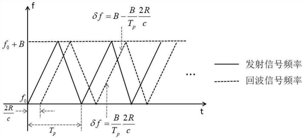
[0005] It can be seen that the general LFM continuous wave radar also needs to process the intermediate frequency signal, resulting in a complex system and more hardware, and also uses digital IQ demodulation, which may cause inconsistency in the amplitude and phase of the IQ two channels, resulting in image frequency In addition, the finite FFT transform will produce spectrum leakage. For high-precision slope ranging, the frequency value extracted by the FFT algorithm is easy to deviate from the real frequency value, which will cause large errors and cause large false alarms; in addition, conventional In the constant false alarm detection method, it is necessary to set the threshold of the signal power for target detection. The threshold needs to be modified according to the change of the signal-to-clutter ratio of each measurement, which makes the slope monitoring work more cumbersome.

Method used


Image

  • High-precision slope monitoring radar target detection and distance measurement method
  • High-precision slope monitoring radar target detection and distance measurement method
  • High-precision slope monitoring radar target detection and distance measurement method

Examples


Embodiment 1

[0081] with f 0=12GHz, τ=1ms (transmission signal pulse width), B=500MHz, when the measurement target is at 1678.9m, carry out simulation calculation according to the method of the present invention, each node result figure is as follows Figure 5-Figure 11 As shown,:

[0082] from Figure 9 It can be seen that the traditional FFT causes spectrum leakage due to signal truncation, while the all-phase FFT complements the breakpoint data and better maintains the continuity of the signal, thereby effectively suppressing the spectrum leakage. from Figure 11 It can be seen that the spectrum envelope refined by the CZT algorithm is more specific, the spectrum resolution is increased, and the peak point of the spectrum can be found better.

Embodiment 2

[0084] with f 0 =12GHz, B=500MHz, τ=1ms, when the measurement targets are at 1200m and 2738m, the results of each node are as follows Figure 12-Figure 18 It can be seen from the comparison of FFT and CZT spectrum refinement diagrams that after spectrum refinement, the envelope is more complete, and the output one-dimensional range image is output as the ranging target result.

[0085] Additionally, from Figure 16 The left and right images of the sampled signal spectrum and Figure 18 Comparing the upper picture and the lower picture, we can clearly see the effect of CZT spectrum refinement. The two frequency points are refined around the two frequency points, showing an obvious envelope and increasing the frequency resolution.

Embodiment 3

[0087] with f 0 =12GHz, B=500MHz, when the measurement targets are at 125.2m, 1234.5m, and 2678.8m, the results of each node are as follows Figure 19-Figure 25 As shown, the detection algorithm cycles the amplitude of each frequency point, normalizes the amplitude of the echo signal after FFT, and further controls the threshold range.

[0088] Figure 20 is the echo signal spectrum, which is added for each target echo signal. Since there are 3 targets, 3 peak frequency points are displayed on each spectrogram. from Figure 23 It can be clearly seen from the comparison chart that the full-phase fft suppresses the spectrum leakage performance. Figure 25 The target one-dimensional range image is the final result output.

[0089] As can be seen from the above, the target detection and ranging method of the present invention can reduce a low-frequency amplification and data acquisition channel while satisfying the slope monitoring function within 5KM, reduce the amount of eq...


PUM


Abstract

The invention discloses a high-precision slope monitoring radar target detection and distance measurement method, and the method comprises the steps: inputting a received signal reflected by a slope into a mixer, enabling the output end of the mixer to be connected with the input end of a low-pass filter, and enabling the output end of the low-pass filter to be connected with the input end of an A / D sampling module; for digital signals at the output end of the A / D sampling module, a signal frequency spectrum is obtained in a leakage-free mode through an all-phase FFT algorithm, a frequency spectrum peak point is accurately detected through a secondary detection algorithm, frequency spectrum refinement is conducted near the frequency spectrum peak point through a CZT algorithm, so that the high-precision value of a wave crest frequency point is measured, and the high-precision value of the wave crest frequency point is obtained. According to the relation between the linear frequency modulation continuous wave difference frequency signal frequency and the distance, the target distance can be obtained through the accurate value of the wave crest frequency point. According to the method, image frequency interference can be avoided, frequency estimation can be optimized, the false alarm probability of target detection can be reduced, the measurement precision of the close-range slope radar can be improved, and the system complexity and the hardware cost can be reduced.

Description

technical field [0001] The invention belongs to the technical field of radar monitoring, in particular to a high-precision slope monitoring radar target detection and ranging method. Background technique [0002] my country is an area where geological disasters frequently occur. According to incomplete statistics, more than 50% of the hidden dangers of geological disasters in our country are landslide hidden dangers. As a kind of geological disaster, landslide has the characteristics of slow formation, sudden occurrence, and strong destructiveness. Therefore, it is difficult for the masses to predict geological disaster landslide monitoring methods. Therefore, high-precision slope monitoring radar is of great significance for monitoring landslides. Therefore, in the field of domestic geological disaster monitoring and prevention, this product has broad application prospects. [0003] The general slope monitoring radar adopts linear frequency modulation continuous wave radar...

Claims


Application Information

Patent Timeline
Patent Type & Authority Applications(China)
IPC IPC(8): G01S13/08G01S13/88G01S7/41G01S7/36G06F17/14
CPCG01S13/08G01S13/88G01S7/414G01S7/36G06F17/14
Inventor 李春苗尹小波罗治郭棋武湛永坚曹毅强孔德君王峰毕晓猛雷彬
Owner HUNAN ZHONGDA CONSTR ENG TESTING TECH
Learn More