Dynamic lower limit sticking direct current side voltage control method of voltage source type converter

A DC side voltage, voltage source type technology, applied in the direction of converting AC power input to DC power output, irreversible DC power input converting to AC power output, electrical components, etc. Difficulty in parameter design, narrow application range, etc., to achieve the effect of good control, good control effect and wide application range

Active Publication Date: 2022-03-22
SHANGHAI UNIVERSITY OF ELECTRIC POWER
View PDF10 Cites 1 Cited by
  • Summary
  • Abstract
  • Description
  • Claims
  • Application Information

AI Technical Summary

Problems solved by technology

[0004] The disadvantages of the prior art ("Dynamic DC Bus Voltage Control Method for Improving the Efficiency of Back-to-Back Converters") include: 1. The prior art needs to calculate the degree of modulation, but the calculation process uses effective value calculations, so that the calculation is only for the period Steady-state value, and there is a delay in the calculation. In addition, the concept of modulation degree is not included in the digital control algorithm adopted by some manufacturers, and an additional complex algorithm is required for virtual construction, and errors will also be introduced in this process; 2. The existing technology requires Adding a proportional-integral regulator is used to generate the reference value of the DC bus voltage, so that the number of proportional-integral regulators in the entire control loop is large, the design of control parameters is very difficult, and it is easy to cause instability; 3. The existing technology limits its use in back-to-back variable flow device, the scope of application is narrow

Method used


Image

  • Dynamic lower limit sticking direct current side voltage control method of voltage source type converter
  • Dynamic lower limit sticking direct current side voltage control method of voltage source type converter
  • Dynamic lower limit sticking direct current side voltage control method of voltage source type converter

Examples


Embodiment

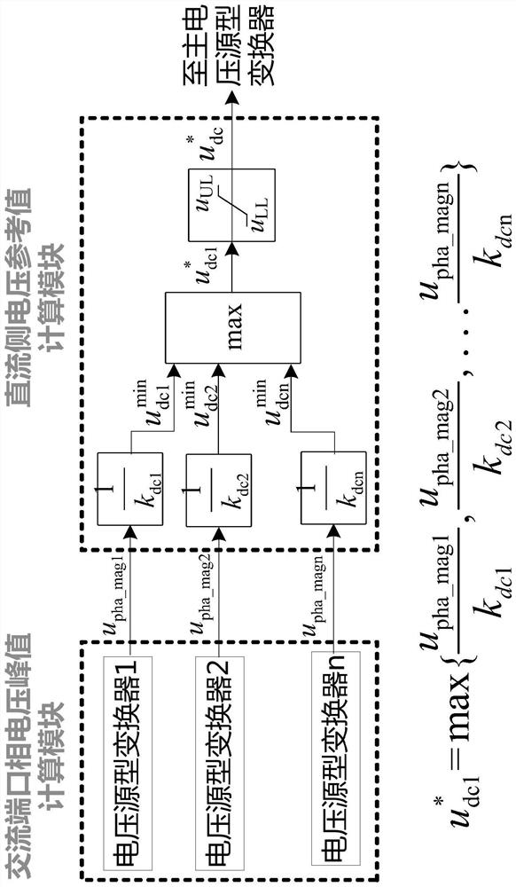
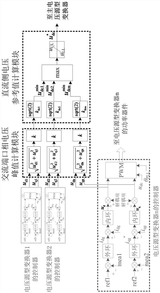
[0032] Such as figure 1 As shown, the basic content of the present invention is: for n sets of voltage source converters with a common DC side voltage, calculate the peak value u of the AC port phase voltage of each voltage source converter pha_mag_i , with u pha_mag_i Divided by the DC side voltage utilization rate k corresponding to the pulse width modulation algorithm adopted by the voltage source converter dc_i , to get the minimum DC side voltage requirement of each voltage source converter Take the maximum value of the minimum DC-side voltage requirements of multiple voltage source converters with a common DC-side voltage, and obtain the DC-side voltage reference command after limiting Will It is provided to the main voltage source converter that controls the DC side voltage to realize the control of the DC side voltage.

[0033] The technical proposal of the present invention is applicable to the situation where a single voltage source converter or multiple volta...


PUM


Abstract

The invention relates to a dynamic lower limit-attached direct-current side voltage control method for a voltage source type converter, which comprises the following steps of: 1, acquiring a phase voltage peak value of an alternating-current port of each voltage source type converter according to the actual condition of common direct-current side voltage operation of one or more voltage source type converters; step 2, based on the alternating current port phase voltage peak value of each voltage source type converter, further obtaining the lowest direct current side voltage demand value of each voltage source type converter; and step 3, taking the maximum value in the lowest direct-current side voltage demand values of all the voltage source type converters, obtaining a direct-current side voltage reference instruction after amplitude limiting, and controlling the main voltage source type converter of the direct-current side voltage by using the direct-current side voltage reference instruction so as to realize the control of the direct-current side voltage. Compared with the prior art, the method has the advantages that a controller system is simpler and more convenient, control parameter design is more flexible, and the obtained steady-state and dynamic control effects are better.

Description

technical field [0001] The invention relates to the technical field of power electronics, in particular to a method for controlling the DC side voltage of a voltage source converter with a dynamic lower limit. Background technique [0002] In voltage source converters, the DC side voltage is directly related to the switching loss and electrical stress of power electronic devices. The higher the DC side voltage, the greater the switching loss and electrical stress. The DC link voltage is usually designed as a high constant value, which usually makes the DC link voltage meet the requirements of all possible operating conditions of the voltage source converter, but not all operating conditions require such a high DC link voltage . [0003] The most similar implementation scheme to the present invention is a dynamic DC bus voltage control method given in the patent "Dynamic DC Bus Voltage Control Method for Improving Efficiency of Back-to-Back Converters". [0004] The disadva...

Claims


Application Information

Patent Timeline
Patent Type & Authority Applications(China)
IPC IPC(8): H02M7/48H02M7/483
CPCH02M7/48H02M7/483
Inventor 贾锋符杨
Owner SHANGHAI UNIVERSITY OF ELECTRIC POWER
Why Eureka
Try Eureka