
Multi-stage slurry bed reactor and working method thereof

A slurry bed and reactor technology, which is applied in the field of multi-stage slurry bed reactors, can solve the problems of low reaction efficiency, easy formation of a dilute phase zone by the catalyst, clogging of the external filter by the catalyst, etc. The effect of simple control and small energy loss

Active Publication Date: 2022-03-25
SOUTH CHINA UNIV OF TECH
View PDF19 Cites 0 Cited by
  • Summary
  • Abstract
  • Description
  • Claims
  • Application Information

AI Technical Summary

Problems solved by technology

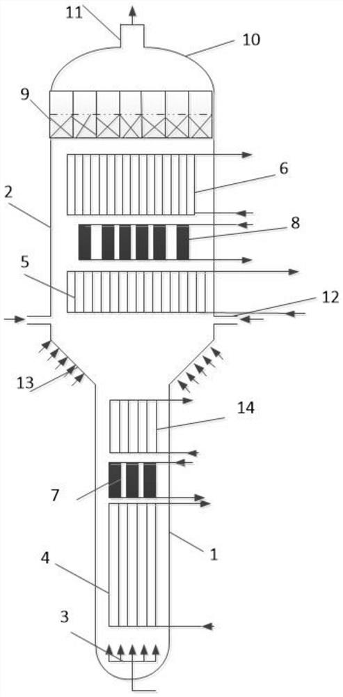
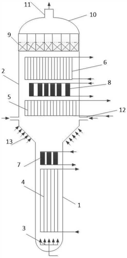
[0003] In order to solve the problems in the existing Fischer-Tropsch synthesis three-phase slurry bed and its reactor that the reaction efficiency is not high, the catalyst is easy to form a dilute phase region, and the catalyst is discharged from the top to block the external filter, etc., the invention relates to a gas generated by a catalyst. Three-phase slurry bed of liquid products and its reactor In the fields of chemical industry and environmental protection, a two-stage reaction is designed by increasing the expansion end and its internal components, and a multi-stage slurry bed reactor and its working method are provided

Method used


Image

  • Multi-stage slurry bed reactor and working method thereof
  • Multi-stage slurry bed reactor and working method thereof
  • Multi-stage slurry bed reactor and working method thereof

Examples


Embodiment

[0053] Embodiment: 200,000 tons of Fischer-Tropsch synthesis reactor comparative situation

[0054] According to the original slurry bed reactor with the same diameter and bottom air inlet, the industrial operation test was carried out. The temperature of the slurry bed reactor was 255°C, the pressure was 2.9MPa, and the superficial gas velocity at the reactor inlet was 0.25m / s. The single-pass conversion rate is 31%, wherein the incoming gas is fresh syngas and cycle gas, and the cycle gas enters from the bottom to occupy the volume occupied by the fresh gas, resulting in a reduction in the conversion rate of the fresh gas, and a small amount of solid particles will be entrained at the top of the reactor. Particles, which will cause these solid particles to enter and may clog the filter, or even reduce the life of the filter, and the fine catalyst is less active, theoretically need to be removed. The reactor of this patent adds an expansion section and changes the air intake ...


PUM

PropertyMeasurementUnit
porosityaaaaaaaaaa

Abstract

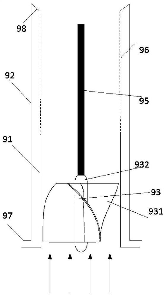
The invention discloses a multi-stage slurry bed reactor and a working method thereof, and relates to a three-phase slurry bed for generating a liquid product from gas through a catalyst and a reactor thereof in the fields of chemical industry and the like. The multistage slurry bed reactor comprises a lower outer shell, an upper outer shell, a gas distributor, a plurality of heat exchangers, a plurality of filters, a separator, an outlet pipe, a circulating gas inlet device and a conical gas distributor, the gas distributor, the heat exchanger and the filter are sequentially and upwards sleeved with the lower outer shell, and the heat exchanger, the filter and the separator inner component are sequentially and upwards sleeved with the upper outer shell; the top cover is arranged between the outlet pipe and the upper outer shell; a conical gas distributor is arranged between the lower outer shell and the upper outer shell; and a circulating gas inlet device is circumferentially arranged at the lower end of the upper outer shell. According to the multi-stage slurry bed reactor, the conversion rate of reactants is increased by adding the multi-stage reaction sections, and top discharge of liquid products and blockage of a subsequent separation system due to escape of catalyst particles are reduced by adding the tubular separator.

Description

technical field [0001] The invention relates to the field of slurry bed reactor equipment, in particular to a multistage slurry bed reactor and a working method thereof. Background technique [0002] Slurry bed reactor is the core technical equipment for turning natural gas or coal-based synthesis gas into liquid fuel. The basic construction process of slurry bed reactor is as follows: synthesis gas enters the gas-liquid-solid three-phase slurry bed from the bottom of the reactor, The synthesis reaction occurs under the action of solid catalyst particles, and the generated liquid products are pumped out from the middle or lower part of the reactor, unreacted synthesis gas and gas products under reaction conditions flow out from the top of the reactor, and part of the separated gas returns through the circulation system To the reactor to continue the reaction, another part of the gas is discharged from the process system as tail gas. The patent CN1233451C discloses a gas-liq...

Claims


Application Information

Patent Timeline
Patent Type & Authority Applications(China)
IPC IPC(8): B01J8/00B01J8/02B01J8/04C10G2/00
CPCB01J8/006B01J8/008B01J8/04B01J8/0285B01J8/0278C10G2/341
Inventor 熊勤钢石战胜李军刘晓雯
Owner SOUTH CHINA UNIV OF TECH
Learn More