Check patentability & draft patents in minutes with Patsnap Eureka AI!

Progressive magnetic pulse forming method and device for thin-wall metal annular shell part

A magnetic pulse forming and annular shell technology, applied in the field of forming large thin-walled metal annular shell parts, can solve the problems of insufficient energy utilization, low energy utilization, insufficient equipment energy, etc., and achieve easy replacement and reduce friction effects. , the effect of high surface quality

Pending Publication Date: 2022-03-25
HARBIN INST OF TECH
View PDF0 Cites 0 Cited by
  • Summary
  • Abstract
  • Description
  • Claims
  • Application Information

AI Technical Summary

Problems solved by technology

The traditional electromagnetic forming process has two disadvantages in forming large parts: one is that the equipment energy is insufficient, and the energy utilization rate in the electromagnetic forming process is very low, and the energy utilization rate of pipe forming is less than 20%; the second is that the coil life is short, forming large parts requires Large coil life, however, during the forming process, the existing coil is prone to failure and deformation due to the influence of magnetic field force and thermal effect

Method used


Image

  • Progressive magnetic pulse forming method and device for thin-wall metal annular shell part
  • Progressive magnetic pulse forming method and device for thin-wall metal annular shell part
  • Progressive magnetic pulse forming method and device for thin-wall metal annular shell part

Examples


Embodiment 1

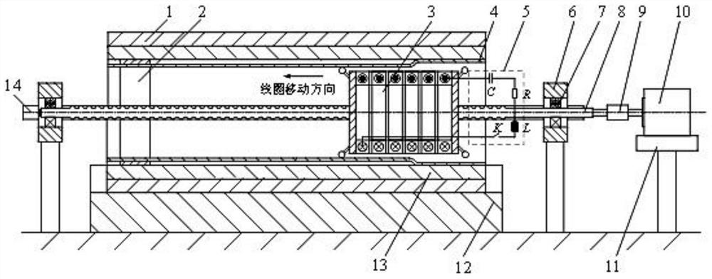
[0047] Such as Figure 1-4 As shown, this embodiment provides a progressive magnetic pulse forming method and device for a thin-walled metal annular shell. Specifically, in this embodiment, the electromagnetic bulging support assembly plastic of the rolled and welded aluminum cylinder is used as an example to describe in detail:

[0048]The thin-walled metal annular shell 4 used in this embodiment is an AA5754 aluminum alloy welding drum, and its structural size is 250mm (outer diameter) × 1mm (wall thickness) × 1500mm (length). The material of the assembled structure to be supported is plastic , the structural size of the assembled plastic pipe is 300 (outer diameter) × 45mm (wall thickness) × 1500mm (length); the material of mold 1 is 45# steel, and the structural size is 300 (inner diameter) × 50mm (wall thickness) × 1500mm ( length), the forming coil is wound by a copper wire 304 with a rectangular cross section of 5mm×7mm, with a total of 20 turns, the outer diameter is 2...

Embodiment 2

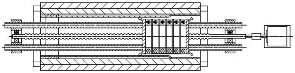
[0071] This embodiment is improved on the basis of Embodiment 1, the improvements are as follows: Figure 5-Figure 7 As mentioned above, this embodiment takes the electromagnetic shrinking and shaping of the rolled and welded aluminum cylinder as an example for illustration:

[0072] The thin-walled metal annular shell 4 used in this embodiment is an AA5754 aluminum alloy welding cylinder, and its structural size is 250mm (inner diameter) × 1.5mm (wall thickness) × 1000mm (length); the forming mold material is 45# steel, and the structure The size is 245mm (radius) × 1000mm (length); the forming coil is wound by a copper wire with a rectangular cross section of 5mm × 7mm, with a total of 15 turns, the inner diameter is 255mm, and the effective length of the forming coil working area is about 105mm (L).

[0073] In this embodiment, the diameter of the above-mentioned rolled and welded aluminum cylinder is reduced to the outer surface of the mold to achieve the purpose of shapin...


PUM


Abstract

The invention discloses a progressive magnetic pulse forming method for a thin-wall metal annular shell part, and relates to the technical field of forming of large thin-wall metal annular shell parts. The progressive magnetic pulse forming method comprises the following steps that a thin-wall metal annular shell and a forming assembly are installed; the coil and the forming assembly are positioned; the gap between the thin-wall metal annular shell and the forming assembly is adjusted to be uniform; first-step forming; follow-up forming is conducted, the position of the thin-wall metal annular shell on a forming assembly is kept unchanged, the coil is moved relative to the thin-wall metal annular shell according to the set feeding step pitch, the non-deformation area of the thin-wall metal annular shell enters the coil working area, and after discharging parameters are set, discharging machining is conducted; and the fifth step is repeated until the whole forming process of the thin-wall metal annular shell is completed. The invention further discloses a progressive magnetic pulse forming device for the thin-wall metal annular shell part. The large thin-wall metal annular shell is driven by the gradual pulse magnetic field force, so that precise forming of the thin-wall metal annular shell is realized.

Description

technical field [0001] The invention relates to the technical field of forming large-scale thin-walled metal annular shell parts, in particular to a progressive magnetic pulse forming method and device for thin-walled metal annular shell parts. Background technique [0002] At present, electromagnetic forming is developing in the direction of high energy, large size and high efficiency. The traditional electromagnetic forming process has two disadvantages in forming large parts: one is that the equipment energy is insufficient, and the energy utilization rate in the electromagnetic forming process is very low, and the energy utilization rate of pipe forming is less than 20%; the second is that the coil life is short, and forming large parts requires Large coil life, however, during the forming process, the existing coil is prone to failure and deformation due to the influence of magnetic field force and thermal effect. [0003] Thin-walled metal ring-shaped casings are a ty...

Claims


Application Information

Patent Timeline
Patent Type & Authority Applications(China)
IPC IPC(8): B21D26/14
CPCB21D26/14
Inventor 于海平程啸董淑辉秦必聪石开宇
Owner HARBIN INST OF TECH
Features
  • R&D
  • Intellectual Property
  • Life Sciences
  • Materials
  • Tech Scout
  • Unparalleled Data Quality
  • Higher Quality Content
  • 60% Fewer Hallucinations
Learn More