Automatic laser cutting equipment for mechanical sheet metal machining

A laser cutting and sheet metal technology, applied in the field of sheet metal processing, can solve the problems of easy deviation, affecting the cutting accuracy of the workpiece, difficult to clean debris and scraps, etc., to enhance cutting accuracy, enhance cutting effect, and ensure stability Effect

Active Publication Date: 2022-03-25
江苏博朗智能装备有限公司
View PDF7 Cites 1 Cited by
  • Summary
  • Abstract
  • Description
  • Claims
  • Application Information

AI Technical Summary

Problems solved by technology

[0003] The current laser cutting machine has the following problems when cutting the workpiece: 1. Most of the common laser cutting machines place the workpiece inside the laser cutting machine, and then directly cut the workpiece, so that the workpiece cannot be fixed. It is easy to deviate during the cutting process and affect the cutting accuracy of the workpiece
[0004] 2. Before the workpiece is laser cut, because the attachments on the surface of the workpiece are not thoroughly cleaned, the dirt and sundries remaining on the upper end of the workpiece are likely to affect the cutting effect of the workpiece, and when the laser cutting machine is working, the cutting debris and The leftovers are difficult to clean up in time, and the slag is easy to stick to the bottom of the laser cutting machine. It is more difficult to clean up later, which will affect the subsequent use effect

Method used


Image

  • Automatic laser cutting equipment for mechanical sheet metal machining
  • Automatic laser cutting equipment for mechanical sheet metal machining
  • Automatic laser cutting equipment for mechanical sheet metal machining

Examples


Embodiment Construction

[0034] The embodiments of the present invention will be described in detail below with reference to the accompanying drawings, but the present invention can be implemented in many different ways defined and covered by the claims.

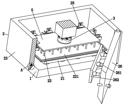
[0035] refer to figure 1 , an automatic laser cutting equipment for mechanical sheet metal processing, comprising a workbench 1, a support unit 2 and a cutting unit 3, the support unit 2 is installed on the upper end of the workbench 1, and the cutting unit 3 is arranged on an external machine tool host.

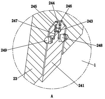
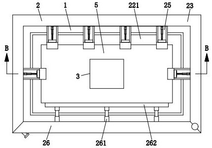
[0036] refer to figure 1 , image 3 , Figure 4 and Image 6 , the support unit 2 includes a support plate 21, a positioning column 22, a U-shaped frame 23, a connecting assembly 24, a pressing assembly 25 and a closed door 26, wherein: the middle part of the upper end of the workbench 1 is provided with a support plate 21 in a detachable manner , the upper end of the support plate 21 is evenly provided with a plurality of positioning columns ...


PUM


Abstract

The invention relates to the technical field of sheet metal machining, in particular to automatic laser cutting equipment for mechanical sheet metal machining, which comprises a worktable, a supporting unit and a cutting unit, the supporting unit is mounted at the upper end of the worktable, and the cutting unit is arranged on an external machine tool host; an existing laser cutting machine has the following problems that a common laser cutting machine cannot fix a workpiece, so that the workpiece is prone to deviation, and the cutting precision of the workpiece is affected; smudginess and sundries left on the surface of the workpiece which is not cleaned are easy to achieve the cutting effect of the laser cutting machine on the workpiece; according to the invention, a workpiece can be fixed in all directions, and the stability of the workpiece during cutting can be ensured, so that the cutting precision of the workpiece can be enhanced; the upper end face of a workpiece can be cleaned, so that the stability of the workpiece during cutting is guaranteed, and the cutting effect of the workpiece is enhanced.

Description

technical field [0001] The invention relates to the technical field of sheet metal processing, in particular to an automatic laser cutting device for mechanical sheet metal processing. Background technique [0002] Laser cutting equipment replaces the traditional mechanical knife with the laser emitted by the laser to realize the function of automatic cutting. Laser cutting equipment is mainly used in sheet metal processing, aviation, electronics, automobiles, machinery and other manufacturing and processing industries. Laser cutting equipment is used in When cutting a sheet metal workpiece, the machine tool host generally drives the cutting head to move correspondingly according to the program written by the worker, so as to cut the workpiece; during the cutting process, when the cutting head passes the workpiece, sparks will be generated, and at the same time, the workpiece will Scraps and scraps left over from cutting will be dropped. [0003] The current laser cutting m...

Claims


Application Information

Patent Timeline
Patent Type & Authority Applications(China)
IPC IPC(8): B23K26/38B23K26/142B23K26/70B23K37/04
CPCB23K26/38B23K26/142B23K26/702B23K37/0435
Inventor 姜大卫
Owner 江苏博朗智能装备有限公司
Why Eureka
Try Eureka