Eureka AIR delivers breakthrough ideas for toughest innovation challenges, trusted by R&D personnel around the world.

Milling cutter grinding machine

A grinding machine and grinding mechanism technology, applied in milling cutters, grinding machine parts, milling machine equipment, etc., can solve the problem of high labor intensity of workers, and achieve the effect of simplifying the feeding process, high work efficiency, and reducing labor intensity.

Active Publication Date: 2022-03-25
GUANGDONG UCAN ROBOT TECH CO LTD
View PDF8 Cites 0 Cited by
  • Summary
  • Abstract
  • Description
  • Claims
  • Application Information

AI Technical Summary

Problems solved by technology

[0005] The technical problem to be solved by the present invention is to provide a milling cutter grinding machine, which can solve the problem of high labor intensity for workers

Method used


Image

  • Milling cutter grinding machine
  • Milling cutter grinding machine
  • Milling cutter grinding machine

Examples


Embodiment Construction

[0037] In order to facilitate the understanding of those skilled in the art, the present invention will be further described below with reference to the embodiments and the accompanying drawings, and the contents mentioned in the embodiments are not intended to limit the present invention.

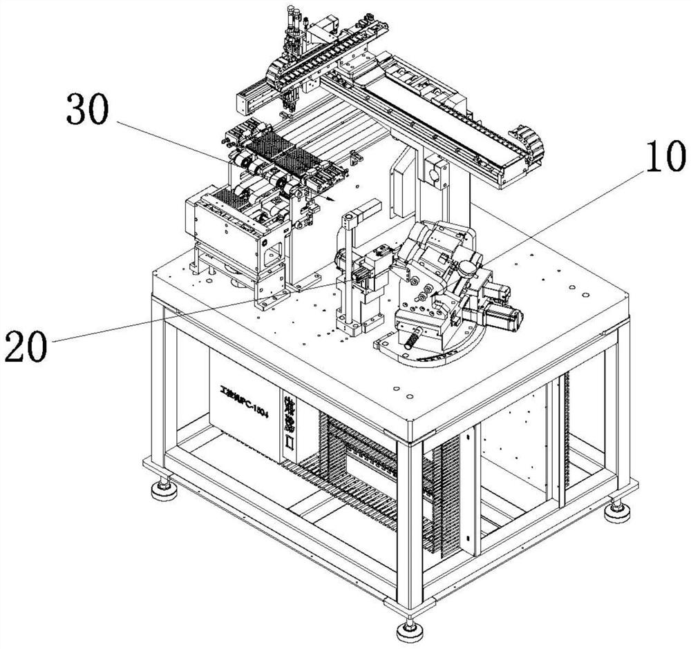
[0038] For the specific implementation of a milling cutter grinding machine of the present application, please refer to figure 1 , the milling cutter grinding machine includes a feeding mechanism 30, a grinding mechanism 10, a pressing mechanism 20 and a transfer robot (not shown) for transferring the feeding rod. Specifically, the grinding mechanism 10 is arranged on the side of the feeding mechanism 30, which can reduce the transfer distance of the material bar, and the pressing mechanism 20 is arranged between the grinding mechanism 10 and the feeding mechanism 30, which is convenient for grinding the material bar. The transfer robot is used to transfer the material bar on the feeding m...


PUM


Abstract

The invention relates to the technical field of milling cutter machining, in particular to a milling cutter grinding machine which comprises a feeding mechanism, a grinding mechanism, a pressing and holding mechanism and a transferring robot used for transferring charge bars. The grinding mechanism is arranged on the side of the feeding mechanism, the pressing and holding mechanism is arranged between the grinding mechanism and the feeding mechanism, and the transferring robot is used for transferring charge bars on the feeding mechanism to a station of the pressing and holding mechanism; in the working process, the transfer robot clamps one material bar from the feeding mechanism and transfers the material bar into the clamping groove, the pressing and holding piece is matched with the clamping groove to press and hold the material bar, and the head of the material bar faces the grinding assembly. Compared with the prior art, by arranging the feeding mechanism and the transfer robot, a previous manual feeding and loading mode is replaced, and by arranging the pressing mechanism, a manual handheld fixing mode is replaced, so that the labor intensity of workers is reduced, the processing consistency of products is ensured, the product quality is improved, and the production time is shortened; therefore, the production efficiency is improved.

Description

technical field [0001] The invention relates to the technical field of milling cutter processing, in particular to a milling cutter grinding machine. Background technique [0002] The structure of the existing milling cutter includes a straight rod and a cutter head formed at the end of the straight rod. The structure of the cutter head is complex and various cutting edges need to be machined according to the needs, and all the current milling cutters are prepared by processing the material bar. The material rod is specifically a cylindrical straight rod and a head located at the end of the straight rod. [0003] At present, for the blade processing of the material bar, the worker generally takes out a material bar from the material tray manually, and then the worker manually moves the head of the material bar close to the grinding mechanism by holding the material bar for blade machining. Factors, there will be the problem of inconsistent workpiece processing quality, and ...

Claims


Application Information

Patent Timeline
IPC IPC(8): B24B3/02B24B41/00B24B41/06
CPCB24B3/02B24B41/005B24B41/06
Inventor 王俊锋黄春雷王哲
Owner GUANGDONG UCAN ROBOT TECH CO LTD
Why Eureka
Eureka Blog
Learn More