Unsteady flow control method based on flutter winglet

An unsteady flow and control method technology, applied in the field of fluid machinery, can solve problems such as increasing system weight, complexity, reducing reliability and engineering practicability, and achieves simple structure, low manufacturing and maintenance costs, and strong engineering practicability Effect

Active Publication Date: 2022-03-25
NANJING UNIV OF TECH
View PDF9 Cites 1 Cited by
  • Summary
  • Abstract
  • Description
  • Claims
  • Application Information

AI Technical Summary

Problems solved by technology

[0005] These technologies have promoted the progress of flow control technology from all aspects. However, these technologies have significant shortcomings in practical engineering applications, mainly reflected in the fact that most unsteady flow control technologies are active flow control and require external energy. To generate excitation energy (air source or power supply), or to generate unsteady mechanical and electrical devices (mostly power supply), this greatly increases the weight and complexity of the system, reduces reliability and engineering practicability

Method used


Image

  • Unsteady flow control method based on flutter winglet
  • Unsteady flow control method based on flutter winglet

Examples


Embodiment 1

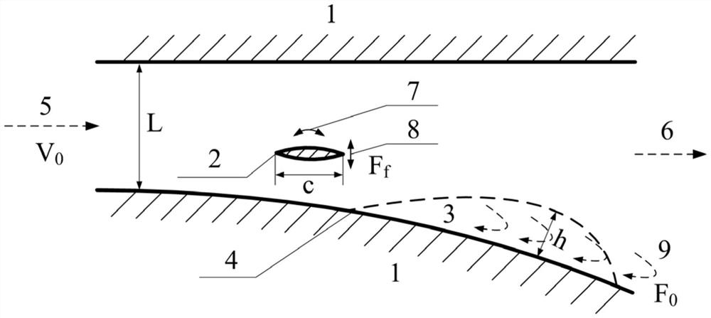
[0026] On the premise that the above implementation steps remain unchanged, the optimization of the mass distribution, damping coefficient, and stiffness coefficient of the flutter winglet 2 can be achieved through theoretical analysis, numerical simulation, and experiments, and through limited trials or experiments.

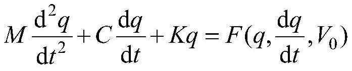
[0027] Taking theoretical analysis as an example, Flutter Winglet 2 can be simplified as an N-dimensional dynamic system (N is greater than or equal to 2), and its motion equation is:

[0028]

[0029] Among them: q is a column vector composed of generalized coordinates on different degrees of freedom of the flutterlet 2; M is the mass matrix of the flutterlet 2; C is the damping coefficient matrix of the flutterlet 2; K is the flutterlet Stiffness matrix of 2; F is the unsteady aerodynamic force on flutter winglet 2; V 0 is the inlet flow rate of the controlled pneumatic component 1. By solving this equation and optimizing M, C, and K at the differential equa...


PUM


Abstract

The invention discloses an unsteady flow control method based on flutter winglets, and belongs to the technical field of fluid machinery. A flutter winglet is arranged near a separation point where a controlled pneumatic component generates flow separation, the flow direction of the flutter winglet is within the range of 5% L in front of and behind the separation point, L is the characteristic length of the controlled pneumatic component, and the distance between the spanwise direction of the flutter winglet and the separation point is 5%-50% of the height h of a separation area. Energy sources such as an external air source or a power source are not needed, a complex air path or a circuit system is not needed, energy can be extracted from a main stream to generate flutter only through the structure of the device, and therefore unsteady excitation used for restraining flow separation is generated, performance indexes such as the pressure ratio, the efficiency, the total pressure recovery and the stability margin of a controlled pneumatic component are improved, and the reliability of the controlled pneumatic component is improved. The system has the advantages of simple structure, no external energy source, high engineering practicability and the like.

Description

technical field [0001] The invention relates to an unsteady flow control method based on flutter winglets, and belongs to the technical field of fluid machinery. Background technique [0002] Since the aviation gas turbine engine pursues high thrust-to-weight ratio and low fuel consumption rate, its various aerodynamic components are at a relatively high aerodynamic load level. Under high aerodynamic load level, various pneumatic components in the state of reverse pressure, such as compressor, diffuser, inlet, and S-bend transition section, are prone to flow separation, resulting in pressure ratio, efficiency, and overall failure of the component. Performance indicators such as pressure recovery coefficient and stability margin drop sharply, which makes it difficult to further improve engine performance. [0003] Therefore, in view of the flow separation phenomenon of reverse pressure pneumatic components, various flow control technologies that can suppress or even eliminat...

Claims


Application Information

Patent Timeline
Patent Type & Authority Applications(China)
IPC IPC(8): B64C23/00
CPCB64C23/005
Inventor 陆惟煜宋林辉高秀敏焦艳梅
Owner NANJING UNIV OF TECH
Why Eureka
Try Eureka