
Thermoelectric cooperation system integrated with steam ejector and operation method

A thermoelectric synergy and injector technology, which is applied to steam engine devices, machines/engines, engine components, etc., can solve problems such as low energy utilization efficiency, influence of power generation output, and large investment in absorption heat pumps, and achieve high energy utilization efficiency and security Heating load and flexible adjustment of parameters

Active Publication Date: 2022-03-25
NINGBO INST OF TECH BEIHANG UNIV
View PDF6 Cites 0 Cited by
  • Summary
  • Abstract
  • Description
  • Claims
  • Application Information

AI Technical Summary

Problems solved by technology

[0003] (1) Peak shaving methods such as electric boiler, bypass main steam, and cylinder cutting only reduce the power generation output of the unit during the low power period. In order to improve the heating capacity, the unit extracts steam for heating during the peak power period, which affects the power generation output during the peak period.
Conventional unit peak-shaving technology faces practical problems such as low energy utilization efficiency and small peak-shaving depth
[0004] (2) The existing heat and power synergy system has problems such as inflexible parameter adjustment, large investment in absorption heat pumps, many temperature difference heat transfer processes, inflexible selection of heat source steam, and no further processing of heat pump driven steam.

Method used


Image

  • Thermoelectric cooperation system integrated with steam ejector and operation method

Examples


Embodiment Construction

[0017] The present invention will be described in further detail below in conjunction with the accompanying drawings and specific embodiments.

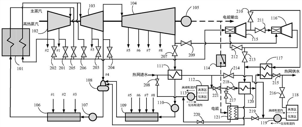
[0018] In order to realize cascaded utilization of energy, the temperature of the heat source and the heated fluid should be reasonably matched in the heat exchange process. For this reason, the present invention adopts the technical scheme of two-stage steam injector cascade ejection steam turbine exhaust to obtain two different types of medium and low pressure. The steam with different parameters can utilize heat energy of different grades in an orderly manner during the heat exchange process. Such as figure 1As shown, a thermoelectric synergy system integrating steam injectors in the present invention includes the main steam side of the boiler 101, the high-pressure cylinder 102 of the steam turbine, the reheat steam side of the boiler 101, the medium-pressure cylinder 103 of the steam turbine, the low-pressure cylinder 104 of the ...


PUM


Abstract

The invention discloses a thermoelectric cooperation system integrated with a steam ejector and an operation method. The system comprises a boiler, a steam turbine high-medium-low pressure cylinder, a first steam exhaust valve, a condenser, a condensate pump, a steam turbine low-pressure heater set, a deaerator, a water feeding pump and a steam turbine high-pressure heater set which are communicated in sequence. The system further comprises various valves, a high-low-pressure steam ejector, a high-low-temperature heat exchanger, an electric heating pump, a high-low-temperature heat storage tank and the like. In the peak period of electric power, the high-low pressure steam ejector, the high-low temperature heat exchanger and the electric heating pump do not work, the low-temperature heat storage tank recycles exhaust steam waste heat of the steam turbine, and the high-temperature heat storage tank is used for supplying heat to a heat supply network; the high-low-pressure steam ejector, the high-low-temperature heat exchanger and the electric heating pump are all put into work in the power off-peak period, working steam of the steam ejector is flexibly and orderly selected according to the heat supply load of a heat supply network, and the high-temperature heat storage tank is adopted for storing redundant hot water for external heat supply in the power peak period. According to the peak regulation process, stepped ordered utilization of energy is achieved, the energy utilization efficiency is high, the peak regulation depth is large, and parameter regulation is flexible.

Description

technical field [0001] The invention relates to the technical fields of thermoelectric synergy, power station peak regulation and steam ejector, in particular to a thermoelectric synergy system and an operation method integrating steam ejectors. Background technique [0002] Due to the strong volatility and anti-peaking characteristics of wind power and photovoltaic power generation, the increase in the proportion of wind power and photovoltaic power generation has brought huge challenges to power grid peak regulation. With the rapid development of clean energy in my country, the problem of the consumption of new energy power generation is still severe, and phenomena such as abandoned wind and light are common. At present, my country's thermal power capacity is overcapacitated, and the annual utilization hours of power generation equipment are low. In the next few years, continuous low-load operation or deep peak-shaving operation of thermal power units will become a norm. ...

Claims


Application Information

Patent Timeline
Patent Type & Authority Applications(China)
IPC IPC(8): F01K13/00F01K13/02F01K21/00F01D15/10F01D17/14
CPCF01K13/00F01K13/02F01K21/00F01D15/10F01D17/145Y02E20/14
Inventor 刘荣堂李璐阳范佩佩王宇黄蕴哲刘明
Owner NINGBO INST OF TECH BEIHANG UNIV
Learn More