
High-speed coupling lens

A coupling lens, high-speed technology, used in the coupling of optical waveguides, light guides, optics, etc., can solve the problems of high-precision lens concentricity, difficult to accurately guarantee lens concentricity, and difficult to high-quality coating. Difficulty, easy to process, the effect of reducing reflection

Pending Publication Date: 2022-03-25
无锡鑫巨宏智能科技有限公司
View PDF13 Cites 0 Cited by
  • Summary
  • Abstract
  • Description
  • Claims
  • Application Information

AI Technical Summary

Problems solved by technology

With the continuous improvement of the transmission rate, there are many problems in the conventional coupling lens: the aspheric lens of the conventional coupling lens is located on both sides of the 45-degree inclined plane, it is very difficult to achieve the concentricity of the high-precision lens, and higher requirements are put forward for injection molding. process requirements; for conventional coupling lenses, there is a relatively deep fiber jack or MT ferrule hole on the side close to the fiber end face, and the aspheric surface on the side of the fiber end face will exist during injection molding and measurement. Great difficulty; whether it is a COB lens or an array lens, as the transmission rate continues to increase, the intensity of the reflected light is required to be small
Both the COB lens and the lens array lens near the fiber end have a certain depth, which makes it difficult to achieve high-quality coating
For example, the publication number CN106855658B discloses a spectroscopic device. The first collimating lens and the second collimating lens are respectively located on both sides of the 45-degree refraction part. It is difficult to accurately ensure the concentricity of the two lenses during injection molding, and the injection molding process requires high requirements.

Method used


Image

  • High-speed coupling lens
  • High-speed coupling lens
  • High-speed coupling lens

Examples


Embodiment Construction

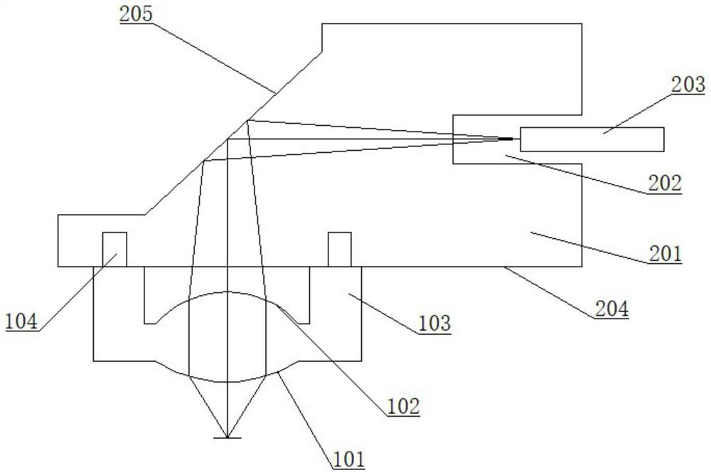
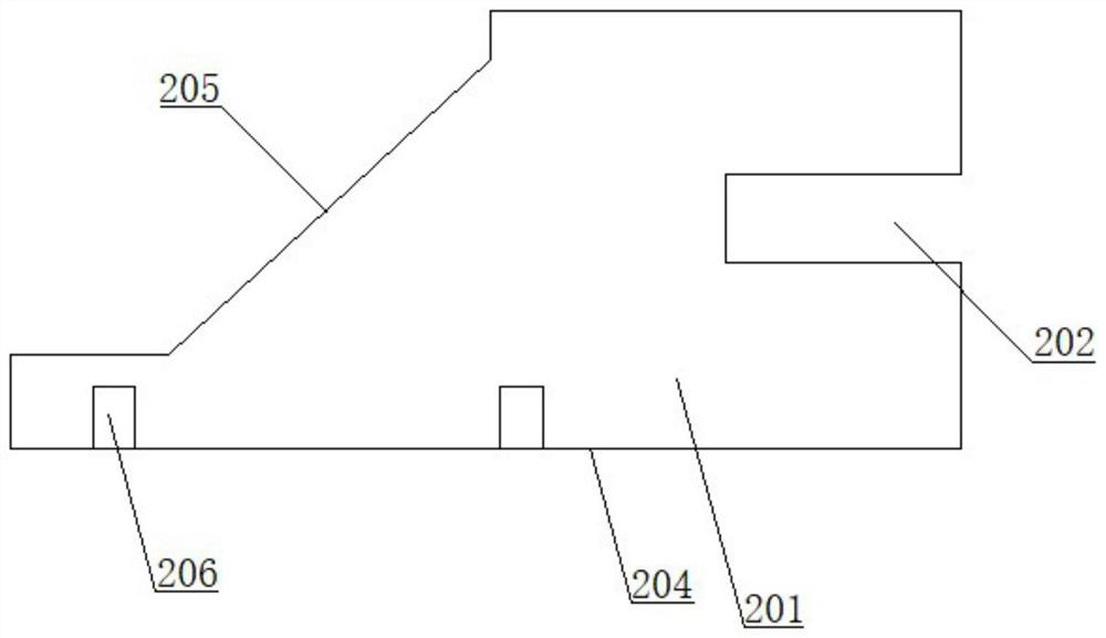
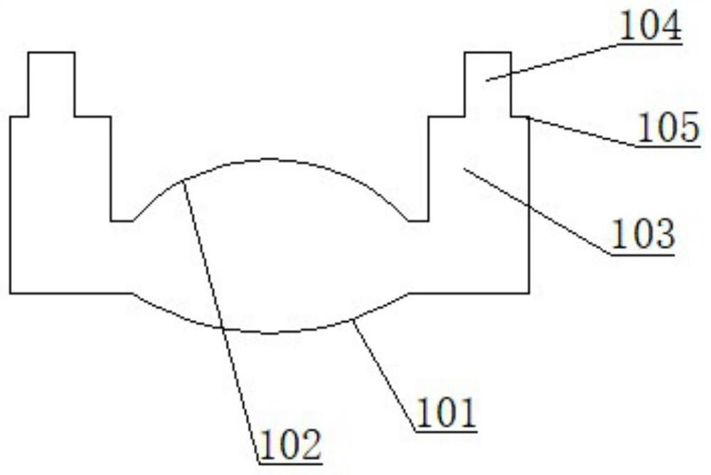
[0019] As shown in the figure, a high-speed coupling lens includes a reflective element 201, a lens, an optical fiber 203 and a light source, wherein the light source is a VCSEL light source, and the lens is provided with an aspheric surface 101 and an aspheric surface 2 102, an aspheric surface 101 and an aspheric surface The surface parameters of the second 102 can be made the same or different according to the needs of use. The lens is installed on one side of the reflective element 201, and the aspheric surface 101 and the aspheric surface 2 102 are all placed on one side of the reflective element, so that the concentricity of the two surfaces can be guaranteed when the lens is made. In addition, the two surfaces When testing or coating, it will not receive interference from other optical surfaces, and it is easy to realize coating and testing.

[0020] The reflective element 201 is provided with a reflective surface 205 corresponding to the first aspheric surface 101 and ...


PUM


Abstract

The invention belongs to the technical field of optical fiber communication, and particularly relates to a high-speed coupling lens which comprises a lens arranged on one side of a reflecting element. The lens is provided with an aspheric surface I and an aspheric surface II; and the reflecting element is provided with reflecting surfaces corresponding to the aspheric surface I and the aspheric surface II. According to the invention, the problems of the conventional coupling lens can be effectively solved, the process difficulty is reduced, and the transmission rate is improved; no other optical surface is arranged between the first aspheric surface and the second aspheric surface to play an interference role, the concentricity of the two surfaces is easily guaranteed, in addition, detection and film coating of the two aspheric surfaces are not interfered by other surfaces, and film coating and detection are easily achieved; the aspheric surface II is independently arranged instead of being arranged in the optical fiber jack, so that the lens does not need to be coated in the jack, and the processing is convenient; by arranging the microstructure, the light intensity of the central area of the VCSEL light beam can be inhibited, the reflection of the whole system is reduced, and the transmission bandwidth is improved.

Description

technical field [0001] The invention belongs to the technical field of optical fiber communication, and in particular relates to a high-speed coupling lens. Background technique [0002] In optical communication, multimode fiber is usually used for short-distance communication, and the light source is 850nm VCSEL light source, and the VCSEL light source is a vertical cavity surface emitting laser, so the coupling lens usually adopts the form of COB or array lens. With the continuous improvement of the transmission rate, there are many problems in the conventional coupling lens: the aspheric lens of the conventional coupling lens is located on both sides of the 45-degree inclined plane, it is very difficult to achieve the concentricity of the high-precision lens, and higher requirements are put forward for injection molding. process requirements; for conventional coupling lenses, there is a relatively deep fiber jack or MT ferrule hole on the side close to the fiber end face,...

Claims


Application Information

Patent Timeline
Patent Type & Authority Applications(China)
IPC IPC(8): G02B6/42
CPCG02B6/4206G02B6/4296
Inventor 钱会明秦玉红
Owner 无锡鑫巨宏智能科技有限公司
Learn More