Electrical automation control box

A technology of electrical automation and control boxes, applied in the direction of program control, computer control, general control system, etc., can solve problems affecting construction efficiency and easy loosening, and achieve the effects of improving construction convenience, preventing loosening, and improving connection stability

Pending Publication Date: 2022-03-25
深圳市龙创华宇科技有限公司
View PDF1 Cites 0 Cited by
  • Summary
  • Abstract
  • Description
  • Claims
  • Application Information

AI Technical Summary

Problems solved by technology

[0003] Among them, the patent No. is CN202010615689.4 for an electrical automation control box. The lifting plate, electric lifting assembly, support seat and operating panel of the present invention are arranged to help push the lifting plate to move upwards when the electric lifting assembly is working. Drive the support base and the operation panel to lift and lower the operation panel, which is convenient for the operation panel to be lifted and lowered during work; the setting of the fixed pipe, branching rod, branching ring, power equipment components and operation panel is conducive to the use of wires to connect the power equipment during work When the components and the operation panel are used, the connecting wires are isolated through the wire splitting ring to prevent the wires from being overheated and affecting the work. Most of the existing wiring boards used in the box for wire connection are the same as the conventional wiring boards. The rotation of the wire achieves the purpose of directly locking the wire or clamping it with the metal plate. However, because the existing wire ends that are sleeved on the wire end are mostly flat metal parts at the end, after being inserted into the wiring board due to lack of pre-set The fixed structure makes the wire end easy to loose after insertion, and in the locking process, one hand is required to fix the cable and the other hand is used to tighten the screw, which greatly affects people's construction efficiency. Therefore, it is necessary to install the existing electrical control box On the basis of further research, a new electrical automation control box is provided

Method used


Image

  • Electrical automation control box
  • Electrical automation control box
  • Electrical automation control box

Examples


Embodiment 1

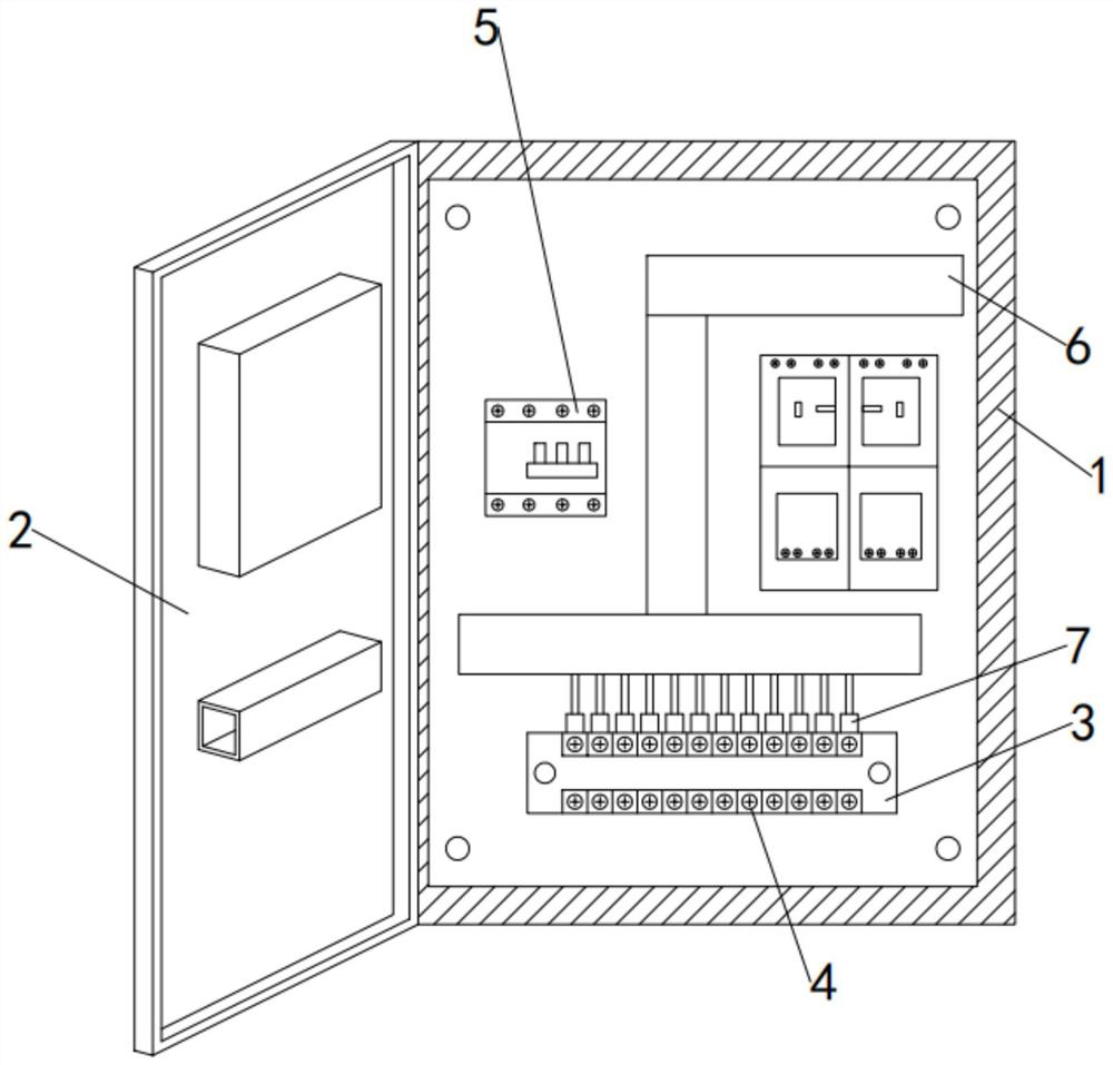
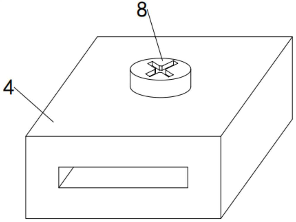
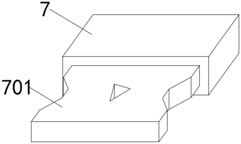
[0030] see Figure 1-4 , in the embodiment of the present invention, the front of the box body 1 is rotatably connected to the box body cover 2, and the inside of the box body 1 is arranged with a wiring board 3, an air switch 5 and a wire management tube 6 in sequence, and the upper and lower sides of the wiring board 3 are embedded and fixed with Terminal 4, and the front of terminal 4 is provided with a rectangular opening, and terminal 7 is embedded in terminal 4, and elastic cards 401 are embedded in the left and right sides of terminal 4, and the cross-section of elastic card 401 is trapezoidal. , the end of the wire end 7 is fixedly connected with an embedded block 701, and the embedded block 701 is arranged in a rectangular shape as a whole, and trapezoidal bayonets are opened on the left and right sides of the embedded block 701, that is, the embedded block 701 after the wire end 7 is connected to the terminal 4 The bayonets on the left and right sides will be locked ...

Embodiment 2

[0034] see Figure 5-7 , in this embodiment, the top of the locking screw 8 is fixedly connected with a top cap 801, and the top of the locking screw 8 top cap 801 is provided with a cross groove to facilitate screwdriver rotation, and the inside of the locking screw 8 is movably connected with an inner rod 802, and the inner rod 802 runs through Lock the center position of the screw rod 8, and the outer wall of the inner rod 802 is connected with the joint of the locking screw rod 8 by setting threads, and the top of the inner rod 802 is provided with a positive hexagonal screw groove, and the outer side of the inner rod 802 is fixed with a helical gear 8021, and locked The inside of the screw rod 8 is located at the junction of the helical gear 8021 and is provided with an active cavity matching the diameter of the helical gear 8021, and the inner wall around the active cavity is provided with threads to mesh with the helical gear 8021. The cross-section of the positioning e...

Embodiment 3

[0038] see Figure 7-8 , in this embodiment, the top of the limit end 803 is fixedly connected with an anti-off plate 8031, the upper surface of the anti-off plate 8031 ​​is fixedly connected with a vertically arranged telescopic spring 804, and the bottom of the inner rod 802 is provided with a cavity for the anti-off plate 8031 slides up and down and telescopic spring 804 stretches and deforms.

[0039] In this embodiment, when the limiting end 803 is driven by the rotation of the inner rod 802 to move down above the groove on the surface of the embedded block 701, the lower surface of the limiting end 803 will stick to the surface of the embedded block 701, but due to the uncertain thread rotation In this way, when the lower surface of the limiting end 803 is attached to the surface of the embedded block 701, the limiting end 803 cannot accurately correspond to the groove on the surface of the embedded block 701 and snap into it, so the inner rod 802 rotates and presses dow...


PUM


Abstract

The invention provides an electrical automation control box, and belongs to the technical field of electrical equipment, the front surface of a box body is rotatably connected with a box body cover, a wiring board, an air switch and a wire management pipe are sequentially arranged in the box body, wiring terminals are embedded and fixed in the upper and lower sides of the wiring board, and the front surface of each wiring terminal is provided with a rectangular opening; a wire end is embedded in the wiring terminal, elastic clamping pieces are embedded in the left side and the right side of the interior of the wiring terminal, and the tail end of the wire end is fixedly connected with an embedded block. The electrical automation control box is provided with the inner rod and the limiting end, after the embedded block is pre-fixed and clamped by rebounding of the elastic clamping piece, the inner rod descends through a screwdriver until the bottom end of the limiting end is close to a groove in the center of the embedded block and is inserted into the groove, and embedding of the limiting end is pressed and matched through descending of the locking screw. The connection stability between the wiring terminal and the wire end can be effectively improved, and the embedded block is prevented from loosening in the use process.

Description

technical field [0001] The present invention relates to the technical field of electrical equipment, and more specifically relates to an electrical control box. Background technique [0002] Electrical automation refers to the operation, control and monitoring of products that can be operated automatically according to a pre-set plan or program without the participation of anyone or few people. Electrical automation refers to the ability to realize mechanical automation, so that mechanical parts It is separated from the direct control and operation of human beings and realizes certain processes automatically. Electrical automation is mainly used in the fields of system operation related to electrical engineering, automatic control, power electronics technology, information processing, experimental analysis, research and development, and electronic and computer applications. In order to ensure the safety of the electric power in the box, most of the existing electrical automa...

Claims


Application Information

Patent Timeline
Patent Type & Authority Applications(China)
IPC IPC(8): G05B19/042
CPCG05B19/0423G05B2219/25257
Inventor 唐端平
Owner 深圳市龙创华宇科技有限公司
Why Eureka
Try Eureka