Energy-saving wax oil hydrogenation device in petrochemical industry
A wax oil hydrogenation and petrochemical technology, applied in petroleum wax refining and other directions, can solve problems such as explosion and hydrogen leakage, and achieve the effects of reducing leakage, reducing shaking and increasing elasticity
- Summary
- Abstract
- Description
- Claims
- Application Information
AI Technical Summary
Problems solved by technology
Method used
Image
Examples
Embodiment 1
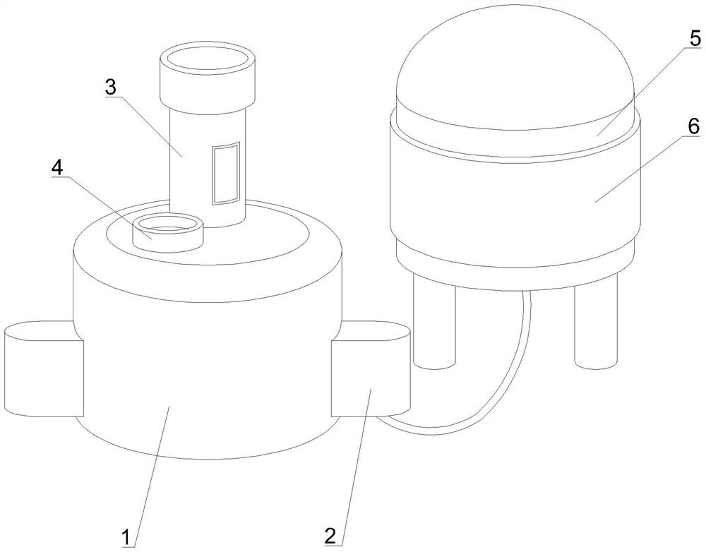
[0043] Such as Figure 1-9 As shown, the present invention provides an energy-saving wax oil hydrogenation device in petrochemical industry, including a wax oil hydrogenation device 1, a circulation collector 2, a pressurizing device 3, a feed port 4, a hydrogen tank 5 and a plastic protective layer 6. The outer surface of both sides of the wax oil hydrogenation device 1 is fixedly connected with a circulation collector 2, the top of the wax oil hydrogenation device 1 is fixedly connected with a pressurizing device 3, and the top of the wax oil hydrogenation device 1 is fixedly connected with There is a feed port 4, and the lower surface of the circulation collector 2 is fixedly connected with an air-conducting hose, one end of the air-conducting hose is fixedly connected with a hydrogen tank 5, and the outer surface of the hydrogen tank 5 is fixedly connected with a plastic protective layer 6 .
[0044] In this embodiment, the wax oil is poured into the interior through the ...
Embodiment 2
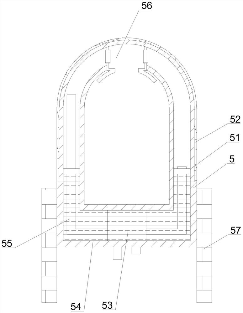
[0047] Such as Figure 1-9 As shown, on the basis of Embodiment 1, the present invention provides a technical solution: preferably, the top of the hydrogen tank 5 is fixedly connected with a built-in plastic layer 51, and the outer surface of the built-in plastic layer 51 is fixedly connected with an outer iron protection layer 52, a circulator 53 is fixedly connected to the inner surface of the bottom of the hydrogen tank 5, the inner surface of the bottom of the hydrogen tank 5 is filled with a filling liquid 54, and gas pipes 55 are fixedly connected to the outer surfaces of both sides of the circulator 53, and the circulator 53 A gas gathering tank is fixedly connected to the top of the gas gathering tank, fixed blocks are fixedly connected to the outer surfaces of both sides of the gas gathering tank, and one end of the air pipe 55 is fixedly connected to the outer surface of the fixed block and extends to the top of the fixed block. The outer iron protection The bottom o...
Embodiment 3
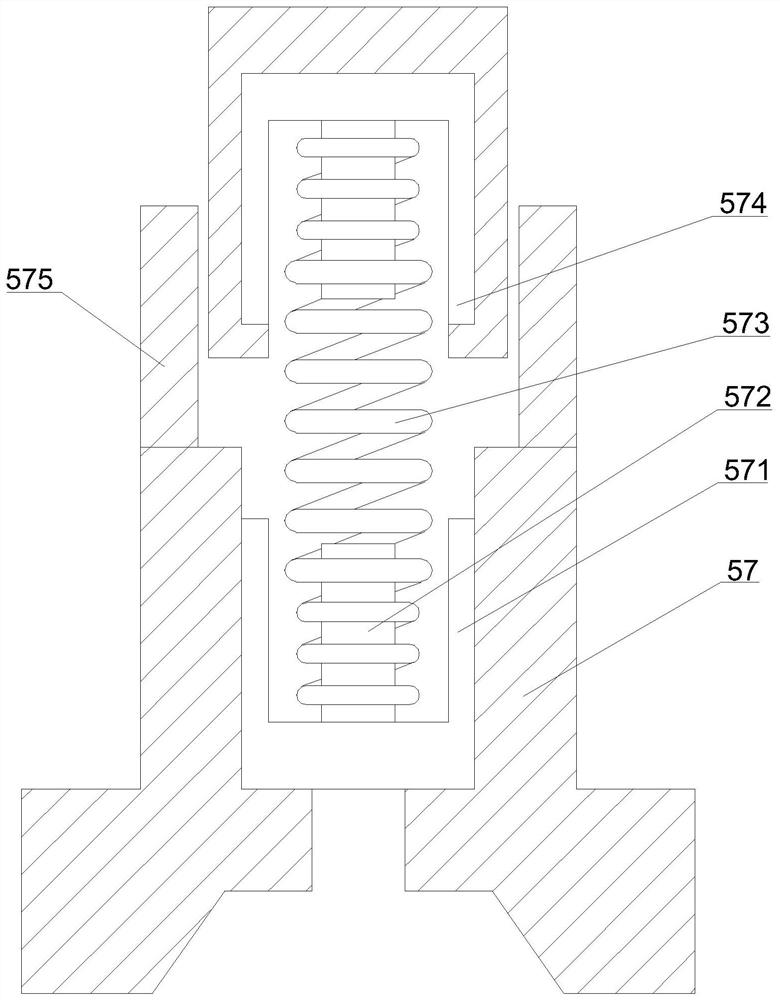
[0050] Such as Figure 1-9 As shown, on the basis of Embodiment 1, the present invention provides a technical solution: preferably, a U-shaped anti-pressure sleeve 571 is fixedly connected to the inner surface of the buffer leg 57, and the inner surface of the bottom end of the U-shaped anti-pressure sleeve 571 A spring column 572 is fixedly connected to the top, a high-voltage spring wire 573 is fixedly connected to one end of the spring column 572, a top sheath shell 574 is fixedly connected to one end of the spring column 572, and an outer guard plate is fixedly connected to the top surface of the buffer leg 57 575.
[0051] In this embodiment, the ground is contacted through the buffer legs 57, and the grounding area is increased by opening the buffer legs 57 to both sides, and the high-voltage spring wire 573 is connected by the spring column 572, and the high-pressure spring wire 573 is used to increase the spring force. Elasticity, and then through the top sheath shell...
PUM
 Abstract
Description
Claims
Application Information
 - R&D
- Intellectual Property
- Life Sciences
- Materials
- Tech Scout
- Unparalleled Data Quality
- Higher Quality Content
- 60% Fewer Hallucinations
Browse by: Latest US Patents, China's latest patents, Technical Efficacy Thesaurus, Application Domain, Technology Topic, Popular Technical Reports.
© 2025 PatSnap. All rights reserved.Legal|Privacy policy|Modern Slavery Act Transparency Statement|Sitemap|About US| Contact US: help@patsnap.com


