Drainage pipeline hot melting installation system

A technology for installing systems and drainage pipes, which is applied in the direction of pipe connection layout, pipe/pipe joints/pipe fittings, mechanical equipment, etc. It can solve the problems of uncontrollable deformation of plastic polyethylene pipes, and achieve controllable heating range, easy connection and uniformity. heating effect

Pending Publication Date: 2022-04-01
北京易成市政工程有限责任公司
View PDF0 Cites 0 Cited by
  • Summary
  • Abstract
  • Description
  • Claims
  • Application Information

AI Technical Summary

Problems solved by technology

[0004] In view of the related technologies mentioned above, the inventor believes that after the plastic polyethylene pipe is sleeved on the iron pipe for a certain length, the iron pipe absorbs the heat of the plastic polyethylene pipe, and the plastic polyethylene pipe cools down rapidly. The plastic polyethylene pipe part on the outside of the pipe is pressed tightly with the iron pipe, and when the plastic polyethylene pipe continues to be pushed to move, it is necessary to apply a large force. Under the large force, the deformation of the plastic polyethylene pipe is uncontrollable.

Method used


Image

  • Drainage pipeline hot melting installation system
  • Drainage pipeline hot melting installation system
  • Drainage pipeline hot melting installation system

Examples


Embodiment 1

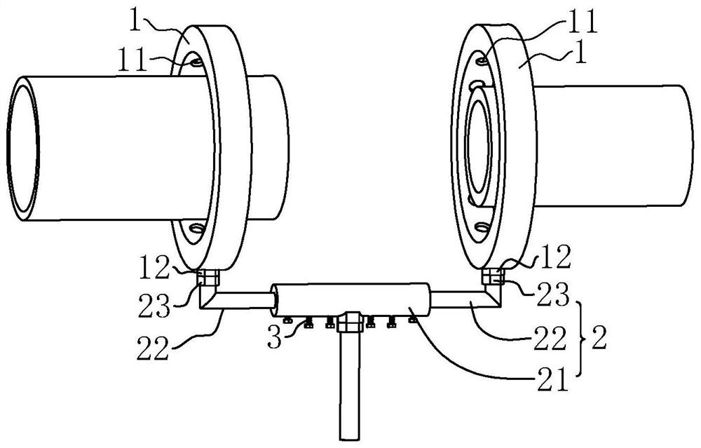
[0039] refer to figure 1 , the hot-melt installation system for drainage pipes includes two heating rings 1 for heating plastic polyethylene pipes and iron pipes respectively. It is arranged coaxially, and the distance between the two heating rings 1 along its axis is adjustable, so that when one heating ring 1 heats the fixed area of ​​the iron pipe, the other heating ring 1 heats the heating area of ​​the plastic polyethylene pipe. Adjustment.

[0040] In this embodiment, a rigid communication pipe 2 is connected between the two heating rings 1, and the communication pipe 2 realizes the coaxial connection between the two heating rings 1. The inner cavity is connected, and the connecting pipe 2 is connected with the gas pipeline. After the gas pipeline sends gas into the connecting pipe 2, the connecting pipe 2 sends the gas into the two heating rings 1 respectively.

[0041] The inner cavity of the heating ring 1 is provided with a fluid channel communicating with the inne...

Embodiment 2

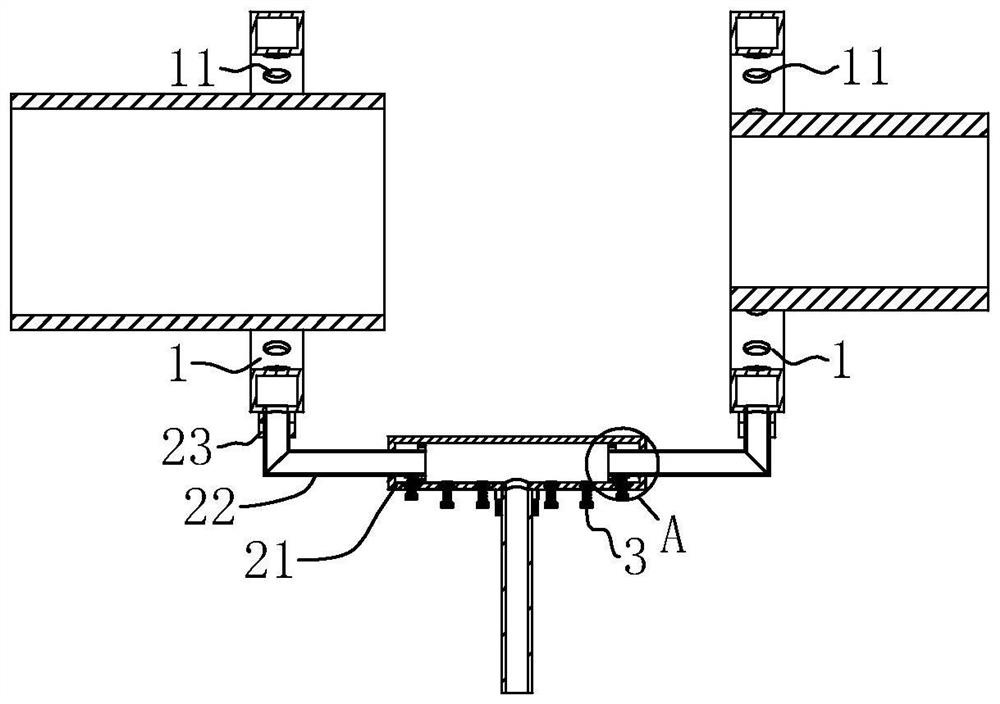
[0058] refer to Figure 4 , The difference between this embodiment and Embodiment 1 is that the drainage pipe hot-melt installation system includes a communication pipe 2, which is a flexible pipe, and the two ends of the communication pipe 2 are respectively connected with the two heating rings 1 through joints, and communicated with each other. Pipe 2 communicates with the gas pipeline. Between the two heating rings 1 is connected a support rod 4 connected to the heating ring 1 with adjustable length at both ends. The support rod 4 includes an inner rod and an outer rod that can slide mutually, and the inner rod and the outer rod slide mutually to realize two heating Adjustment of ring 1 axial distance.

[0059] As an optional solution, a flow regulating valve 5 is provided between the communication pipe 2 and the heating ring 1 , and in this embodiment, one flow regulating valve 5 is provided to control the amount of gas entering one of the heating rings 1 . In another em...


PUM


Abstract

The invention relates to a drainage pipeline hot melting installation system, and relates to the field of pipeline installation engineering, the drainage pipeline hot melting installation system comprises two heating rings with inner cavities provided with channels, the two heating rings are coaxially arranged, the inner sides of the heating rings are provided with a plurality of heating holes arranged at intervals, and the heating holes communicate with the inner cavities of the heating rings; a communicating pipe used for feeding combustible gas into the inner cavities of the heating rings is connected between the two heating rings, the communicating pipe is communicated with the inner cavities of the two heating rings, and the distance between the two heating rings along the axes of the two heating rings is adjustable. The hot melting connection structure has the effect of facilitating hot melting connection between the plastic polyethylene pipeline and the iron pipe.

Description

technical field [0001] The application relates to the field of pipeline installation engineering, in particular to a drainage pipeline hot-melt installation system. Background technique [0002] In urban construction, the laying of water supply and drainage pipes is particularly important to the city's water supply and drainage system. Polyethylene pipes for water supply and drainage are a common pipe. Hot-melt welding is often used for installation and connection of polyethylene pipes. [0003] When it is necessary to install plastic polyethylene pipes and rigid iron pipes or joints, the plastic polyethylene pipes need to be heated to soften them, and then the plastic polyethylene pipes and rigid iron pipes move relative to each other along the axial direction and are sleeved on the rigid iron pipes After the plastic polyethylene pipe is cooled, the plastic polyethylene pipe is connected to the rigid iron pipe or joint. [0004] In view of the related technologies mentione...

Claims


Application Information

Patent Timeline
Patent Type & Authority Applications(China)
IPC IPC(8): F16L47/02
Inventor 陈静张树王常利郝艳伏杨武郑德亮冯俊成
Owner 北京易成市政工程有限责任公司
Why Eureka
Try Eureka